Amplifier Classes
Amplifier classes are categories that describe how an amplifier handles the combination of input signal amplification, linearity, power-efficiency and electromagnetic interference to at a given size and cost.
Classification helps engineers, designers, and consumers with essential information about how a particular amplifier operates, and what trade-offs it makes in terms of efficiency, linearity, distortion, size, and cost
Goal of a Power Amplifier (PA)
An amplifier should add minimal distortion while driving a load at minimal quiescent power within acceptable electromagnetic interference. The power delivered to load is much higher than the input power taken from source.
Goal of a Low Noise Amplifier (LNA)
An amplifier should add minimal noise and distortion while providing maximum signal gain at the output at low quiescent power. Most of the time the low noise amplifier’s load is not heavy so the power requirements are not stringent as a power amplifier.
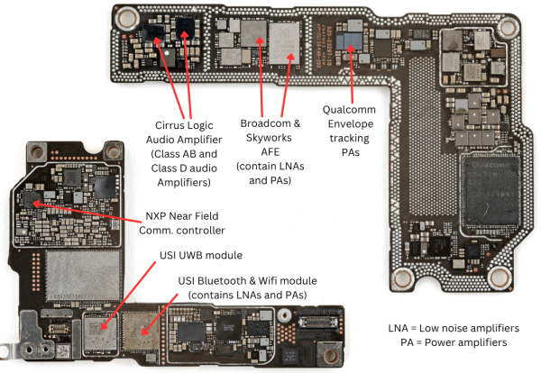
Power Efficiency in Amplifier
Ideally, if the input signal is zero (meaning output signal is zero), the power consumed by the amplifier should be zero as well. However, in reality the amplifier needs quiescent current to provide required gain and speed. It is defined as the ratio of average power delivered to load and total power consumed from the supply.
Conduction angle
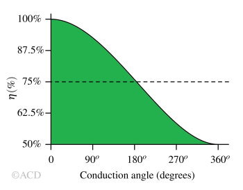
The conduction angle is the portion of the input signal cycle (measured in degrees or radians) during which the amplifier’s active device (like a transistor) conducts current and remains “on.” It essentially tells you for how much of the input waveform the device is actively amplifying.
Efficiency vs Conduction angle
Class A amplifier
A Class A amplifier is a type of linear amplifier in which the output device conducts current for the entire 360° of the input signal cycle. The transistor is consuming power even if input signal is zero.
More about class A amplifiers : Class A amplifiers
Operating principle
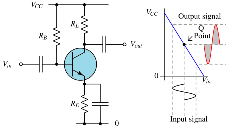
The device is always "on” amplifying the full waveform without any part of the cycle being cut off. The transistor is set at a Q-po\int, typically in the centre of its transfer (load) line, ensuring that as the input signal moves positive and negative, the output remains in the linear region. This produces an undistorted amplified output.
Unlike Class B amplifiers, there is no "dead zone" during zero-crossing; since the output device never turns off. Therefore, crossover distortion is avoided. Max efficiency = 50%. Real world power efficiency is 20-30%.
Pros and Cons
- This operating condition ensures the highest linearity (lowest distortion) among all amplifier classes, making Class A the standard for applications requiring maximum fidelity and minimal signal alteration
- The circuit complexity is minimal across all the amplifier classes.
- The power efficiency is the lowest among all other classes of amplifiers.
Applications
- Very high linearity applications
- Due to presence of minimal number of transistors it is preferred in making low noise amplifiers (LNAs)
Class B amplifier
A Class B amplifier is characterized by its output devices (transistors) each conducting for exactly half (180°) of the input signal cycle, resulting in significantly higher efficiency compared to Class A amplifiers but also introducing distortion (crossover distortion).
Operating principle
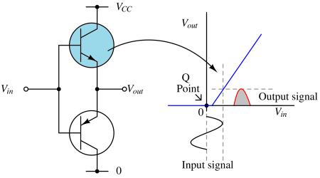
The circuit uses a push-pull configuration with two complementary transistors (typically one NPN and one PNP, or similar types for MOSFETs). Each transistor is biased at cutoff so there is no current when there’s no input signal. For a sinusoidal input, The NPN (or N-channel) device conducts and amplifies the positive half-cycles. The PNP (or P-channel) device conducts and amplifies the negative half-cycles.
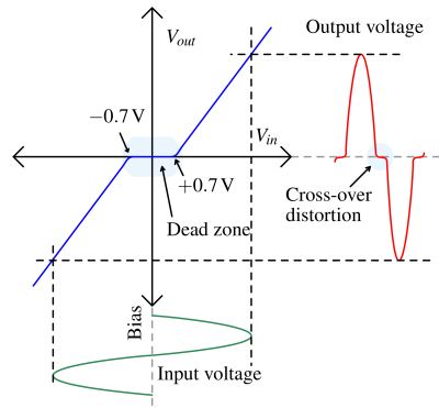
Dead zone in Class B amplifiers - At the po\int where the signal crosses zero and “hands off” between transistors, neither may be conducting momentarily. This region when none of the transistors are conducting is called dead zone. The input is moving but output is not moving. Therefore, the output fails to replicate the input properly. Theoretical maximum up to 78.5%, much higher than Class A amplifiers.
Pros and Cons
- Much improved power efficiency over Class A amplifiers.
- Lower heat production, smaller heatsinks and enclosures required.
- Significant crossover distortion due to dead zone at the zero-crossing (solved in Class AB amplifiers).
- Slightly more complex than Class A due to the need for a push-pull output stage and phase-splitting input stage.
Class AB Amplifier
A Class AB amplifier blends the strengths of Class A (high linearity) and Class B (high power efficiency) to achieve a favourable balance between efficiency and linearity.
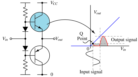
Operating principle
In class AB amplifiers, the "dead zone" is removed. To eliminate the “dead zone” in class B and improve the distortion, each transistor is slightly forward-biased (using extra diode voltage drops) resulting in overlapping conduction near zero-crossing. Near the zero-crossing of the input waveform, both devices are "on" at the same time, unlike pure Class B where both would be "off". Both conduct for more than 180° but less than 360° of the input signal cycle. For small signals, both transistors conduct simultaneously (like Class A, for low distortion).
Since output to moving appropriately for every input, the dead zone is removed. Therefore, the crossover distortion is reduced significantly. Max power efficiency is 50 – 78%.
Pros and Cons
- By keeping both transistors slightly on during waveform zero-crossings, Class AB amplifiers maintain good signal linearity and are suitable for high-fidelity audio and professional sound applications (pro-audio).
- While not as efficient as Class D and Class B, Class AB amplifiers are significantly more efficient than Class A designs, often achieving up to 50–78% efficiency, meaning less power wasted as heat and smaller cooling requirements
- Class AB amplifiers do not produce electromagnetic interference.
- They still draw some power even with no signal input, unlike pure Class B designs.
- The need for additional components for biasing and thermal tracking makes them a bit more expensive and complex than simple Class A or Class B amps.
Applications
Class AB amplifiers are widely used in audio applications where both efficiency and sound quality are important. They do not generate electromagnetic interference.
Class C amplifier
A Class C amplifier is a power amplifier in which the active device (such as a transistor) conducts for less than 180° (less than half) of the input signal cycle. This short conduction angle results in very high efficiency, but also introduces significant distortion, making Class C amplifiers unsuitable for audio applications and ideal for radio frequency (RF) uses where signal reconstruction is handled with tuned circuits.
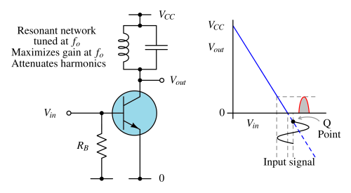
Operating principle
The transistor is biased well below cutoff, so it only turns on briefly during high input voltage portions of the waveform. The conduction angle is typically in the range of 80° to 120°. As a result, the output is a series of current pulses, rather than a faithful reproduction of the input waveform. Most of the input cycle results in zero collector current. To obtain a usable output, a tuned LC resonant circuit (tank circuit) is used at the output. This circuit filters out the harmonics and reconstructs a sine wave at the carrier frequency desired for RF transmission
Pros and Cons
- Extremely high efficiency (much less heat; smaller size for a given output power).
- Ideal for high-frequency, fixed-frequency RF applications
- Extremely high distortion and non-linearity; virtually unusable for audio or applications where the output must closely match the input.
- Requires carefully tuned output circuits to recover the intended signal.
- Generates significant unwanted harmonic content, demanding good filtering.
Class D amplifier
A Class D amplifier is a switching-mode power amplifier (SPDT switch) that achieves high efficiency by rapidly switching its output devices fully on or off, rather than operating them in their linear region as in traditional amplifiers like Class A or AB. It can be thought as a switched class B amplifier.
Operating principle
The analog input audio signal is converted into a train of pulses using pulse width modulation (PWM) or similar modulation techniques. The width (duration) of these pulses corresponds to the amplitude of the input signal at any moment. These PWM pulses then drive the output stage (often MOSFET transistors) which act as high-speed electronic switches, rapidly turning fully on or fully off.
Because the output devices are either fully on (zero resistance, P = I2R = 0) or fully off (zero current), the power dissipation in these devices is minimal, resulting in very high efficiency. The output, which is a series of high-frequency pulses, is passed through a low-pass filter (usually an LC low pass filter) to reconstruct the analog waveform that can drive a speaker.
More about class D amplifiers : Class D amplifiers
Pros and Cons
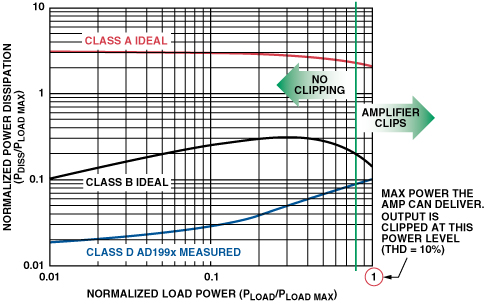
- High Efficiency: Class D amplifiers can achieve efficiencies above 90% because the output transistors operate as switches, minimizing power wasted as heat. This leads to cooler operation and less need for large heat sinks.
- Compact Size & light weight for high power audio applications: Due to their efficiency, they generate less heat, allowing for smaller form factors—ideal for portable, automotive, and space-constrained applications.
- Cost Efficiency: Less power wasted as heat means lower operating costs (energy savings) and less spent on materials for cooling.
- Electromagnetic Interference (EMI): The fast switching action produces radio-frequency interference, which can affect nearby sensitive electronics if not properly filtered/shielded.
- Less Ideal for Some Applications: Not typically used in very high fidelity, low-level audio preamps, or certain RF/power applications where linear performance is critical.
Class E amplifier
A Class E amplifier is switching-mode power amplifier primarily used in RF-applications, where the transistor operates as a switch, either fully on or off. Its key feature is a specially designed load network that shapes the voltage and current waveforms at the transistor to minimize the simultaneous occurrence of high voltage and high current (minimising product of current and voltage), thereby greatly reducing power dissipation during the switching transitions.
Operating principle
The transistor acts as a switch driven by a square wave or pulse-like signal. The load network, which typically includes inductors, capacitors, and the transistor's own parasitic capacitances, is designed so voltage across the transistor drops to zero before it switches on (zero-voltage switching) and current is minimal at turn-off (zero-current switching). This waveform shaping reduces overlap between voltage and current, significantly lowering switching losses compared to other amplifier classes like Class B or C. The shunt capacitance (parasitic or added) and series-tuned circuit components form a resonant network that effectively channels stored energy to the load instead of dissipating it as heat.
Pros and Cons
- Extremely high efficiency, often exceeding 80-85%, surpassing Class B or C amplifiers at similar frequencies and power levels.
- Usually operates in narrow-band or fixed-tuned frequency bands due to presence of tuned loads. Common in RF and microwave frequency ranges.
- Results in minimal power loss during transistor switching transitions because voltage and current waveforms are carefully engineered to avoid overlap.
- Generates significant harmonic content, similar to Class B amplifiers, requiring appropriate filtering.
| Class D | Class E | |
|---|---|---|
| Frequency range | DC-20kHz | > 3MHz and < 10GHz |
| Type of load | Low pass filter | Tuned LC filter |
| Feedback loop | Present | Absent |
| Applications | Audio power amplifiers | RF power amplifiers |
Class F amplifier
A Class F amplifier is a type of power amplifier designed to maximize efficiency by shaping the voltage and current waveforms at the output device using harmonic tuning. It is an extension of class B amplifier to improve the efficiency beyond 78%. This is achieved through a load network composed of multiple resonant circuits tuned to specific harmonics of the fundamental frequency, which reshapes the transistor’s voltage waveform towards an ideal square wave and the current waveform towards a half-sinusoid.
Operating principle
The active device is biased near a nonlinear region (transistor dependent) so that harmonics are generated. Odd-harmonics are reshaped and Even-harmonics are suppressed using the resonant loads tuned at each harmonic. Class F amplifier is not switch-mode power amplifier. Ideally, maximum efficiency depends achieved can be 100% depending on how many harmonics are tuned to create the square wave. Class F waveforms have higher efficiency then corresponding sinusoidal waveforms because the squared voltage is at zero for a longer period of time while the current is on. Efficiency at high frequency is limited by device parasitics.
| Class A | Class B | Class C | Class F | |
|---|---|---|---|---|
| Frequency range | Any frequency | < RF | RF | RF |
| Type of load | Tuned circuit may not be required because output is linear. | Low pass filter | High Q LC resonant circuit tuned only at fundamental | High Q resonant circuits tuned at fundamental & harmonics. |
| Transistor collector (or drain) voltage waveform | Sinusoid | Half-rectified sinusoid | Partial rectified sinusoid | Near Square wave to improve efficiency |
| Efficiency | <50% | <78% | <100% | <100% |
| Transistor Conduction angle | 360° | 180° | < 180° (100° - 150°) | 180° |
Class G amplifiers
A Class G amplifier is a type of linear amplifier that improves efficiency over conventional Class AB designs by incorporating two or more power supply voltage rails. The key innovation is that as the input signal varies, the amplifier dynamically switches between these different voltage rails—using a lower voltage for small signals and switching to a higher voltage rail only when the output signal demands it.
Class H amplifiers
A Class H amplifier is a type of linear amplifier that enhances efficiency beyond Class AB and Class G by dynamically modulating its power supply voltage. The supply rails "track" the output signal, providing a voltage just a few volts higher than the signal at any instant, rather than remaining fixed or switching between a few discrete rails. This minimizes wasted energy as heat, especially when the amplifier is used for signals (like music) with frequent, rapid changes in amplitude. These are similar to Envelope tracking power amplifiers.
By maintaining a small and nearly constant voltage drop across the output devices, Class H amplifiers reduce power dissipation across all output levels—not just during peaks, as in Class G designs.
| Property | Class AB | Class G | Class H |
|---|---|---|---|
| Power supply rails | Single (fixed) | Multiple discrete supply voltage levels (selected as needed) | Continuous analog Supply voltage tracking the peak signal. |
| Efficiency | Moderate | High | Highest |
| Heat generation | Moderate | Low | Lowest |
| Complexity | Low | High | Highest |
| Audio Linearity / Fidelity | High | High | High |
Advanced topics
Envelope Tracking Power amplifiers
Envelope Tracking is a more advanced class H amplifier. It is precise, fast-tracking technique designed for RF amplifiers, where the voltage supplied follows the fine variations of the RF signal's envelope in real time for maximum efficiency—and to meet strict spectral requirements in wireless systems.
Doherty amplifiers
A Doherty amplifier is a type of RF (radio frequency) power amplifier designed to achieve high efficiency, especially when amplifying signals with high peak-to-average power ratios, which are common in modern wireless communications and broadcasting
Summary of amplifier classes
| Class | Linearity | Ideal maximum Power Efficiency | Practical Power efficiency | Electromagnetic interference | Design and system Complexity | Suitable applications | Conduction angle with respect to input signal (sinusoid) |
|---|---|---|---|---|---|---|---|
| A | Linear | 50% | <25% | No | Simple | Used as LNA, not used as PA | 360° |
| B | Non-linear | <78% | <50% | No | Simple | Power amplifiers | 180° |
| AB | Linear | < 78% | 35-60% | No | Complex | AM, lower-order Digital | 180°-360° |
| C | Non-linear | 100% | 75% | No | Simple | AM, QPSK | <180° |
| D | Switched | 100% | 75% | Yes | Complex+ | Audio amplifiers | 180° |
| E | Switched | 100% | 90% | Yes | Complex+++ | RF | ~180° |
| F | Non-linear | 100% | 80% | No | Complex+++ | RF | ~180° |
| G | Linear | 78% | 64% | No | Complex++ | Audio amplifier | 180°-360° |
| H | Linear | 78% | 74% | No | Complex++ | Audio amplifiers | 180°-360° |