Light Dependent Resistor
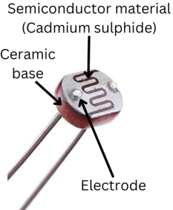
A Light Dependent Resistor (LDR), also known as a photoresistor, is a type of passive electronic component that exhibits a change in its electrical resistance based on the intensity of incident light. LDRs are typically made of semiconductor materials, often composed of cadmium sulfide (CdS) or other similar compounds. LDRs are commonly used in various electronic circuits and devices for light-sensing applications.

Operating principle of Photoresistor
LDRs are made of semiconductor materials that have a high resistance in the dark and a lower resistance when exposed to light. In the absence of light (in darkness), the semiconductor material within the LDR has a high resistance, meaning it restricts the flow of electric current through it. This high resistance is due to the absence of photon (light particle) interactions with the semiconductor material. When light falls on the LDR, the photons cause some of the electrons in the material to move from the valence band to the conduction band, creating electron-hole pairs. These free electron-holes pair now contribute to the conduction. As more photons strike the LDR and generate more electron-hole pairs, the material's resistance decreases further.
Circuit symbol of a Light dependent resistor

The symbol for an LDR in an electronic circuit is a resistor-like shape with two arrows pointing at it, representing the variation in resistance with light.
What is the difference between a photoresistor and a photodiode?
A photoresistor is purely a passive device because they do not possess a PN junction. The incidence of light on a photoresistor/LDR does not form a voltage drop and thus cannot be used as a voltage source to draw current. While a photodiode forms a voltage drop which can supply current when a load is connected to it.
Applications of photoresistor/LDRs
- Light Sensing: LDRs are commonly used in light-sensitive applications such as streetlights that automatically turn on at dusk and off at dawn.
- Photography: They are used in cameras to measure light levels and adjust exposure settings.
- Security Systems: LDRs can be used in security systems to detect changes in ambient light conditions. A sudden drop in light intensity, caused by the presence of smoke or flames, triggers an alarm.
- Solar Panels: Arrays of LDRs are sometimes part of solar panel systems to track the position of the sun and optimize energy collection.
- Robotics: In robotics, LDRs can be used for obstacle detection or for recognizing patterns and shapes based on light and shadow.
- Consumer Electronics: LDRs are used in consumer electronics like automatic night lights, which turn on when it gets dark, and turn off when it's b\right.
- Automotive Applications: Some vehicles use LDRs in automatic headlight systems, which switch between high and low beams based on the ambient light and the presence of other vehicles.
- Industrial Automation: In industrial settings, photoresistors are used in various applications, such as monitoring conveyor belt operations, sorting systems, and quality control processes based on light levels.
Example : LDR based daytime energy saving circuit
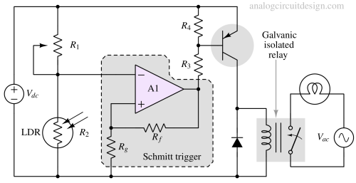
A photoresistor, also known as a light-dependent resistor (LDR), can be used in a simple electric lamp control circuit to automatically turn the lamp on or off based on the ambient light levels. Here's a basic circuit diagram and the components needed:
- Photoresistor (LDR)
- PNP transistor (e.g., 2N3906)
- Resistor (R1, 10k Ohms)
- Resistor (R3, 8.3k Ohms)
- Resistor (R4, 700 Ohms)
- Opamp as Schmitt trigger (A1, LM358)
- Lamp (with socket and appropriate voltage rating)
- Power supply (e.g., 9V battery) or a full-wave rectified DC
- Relay

Here's how the circuit works:
The photoresistor (LDR) is connected in series with a resistor (R2) and the lamp. The junction is connected to the inverting pin of the opamp. The opamp is configured as a Schmitt trigger-based comparator. If sunlight falls on the LDR, the resistance drops to a very low value which pulls down the junction node (R1 and R2) to near zero. This leads to the output of A1 going near the positive rail which turns off the PNP transistor. When the PNP is off, the relay is de-energized and the lamp turns off.
If it is darkness, the resistance offered by R2 is very high. The inverting pin of the opamp A1 is higher than the non-inverting pin of the opamp. This leads to saturation of the opamp's output near the negative rail, which pulls down the PNP transistor base. Now PNP turns on which energizes the relay and the lamp turns on.