RC (resistor-capacitor) circuit
A resistor-capacitor (RC) circuit is a combination of a resistor and a capacitor connected in series or parallel to a voltage or current source. The resistor restricts the flow of current in the circuit, creating a voltage drop across it proportional to the current passing through. The capacitor, on the other hand, stores electrical energy in the form of an electric field when charged. When an RC circuit is connected to a voltage source, the capacitor charges up gradually through the resistor until it reaches its maximum charge (asymptotically). This charging process follows an exponential curve, characterized by a time constant, τ = RC, where R is the resistance and C is the capacitance. This time constant defines how quickly the capacitor charges or discharges.
Types of RC circuit
RC circuit depending on the way the resistor and capacitor are connected can be classified in the following ways:
- Series RC circuit
- Parallel RC circuit
Series RC circuit forming a low pass filter
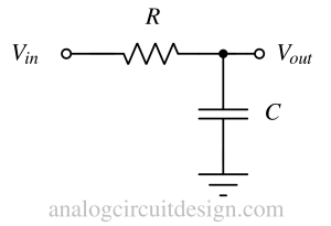
Step response
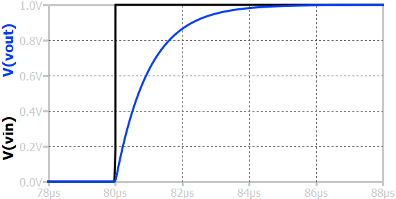
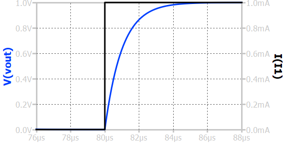
When a step input voltage is applied to a first-order RC low-pass circuit, the output voltage across the capacitor does not change instantaneously but gradually rises toward the final steady-state value. Initially, the capacitor behaves like a short circuit, and the output voltage is zero. As time progresses, the capacitor charges through the resistor, and the output voltage increases exponentially following the expression \(v_o(t) = V_{in}(1 - e^{-t/RC})\), where RC is the circuit’s time constant. The time constant represents the time required for the output to reach approximately 63.2% of its final value. After about five time constants, the capacitor is nearly fully charged, and the output voltage equals the input voltage, indicating that the circuit has reached steady state. This slow charging behavior demonstrates the low-pass characteristic—allowing slow (low-frequency) variations to pass while attenuating rapid (high-frequency) changes.
Frequency response
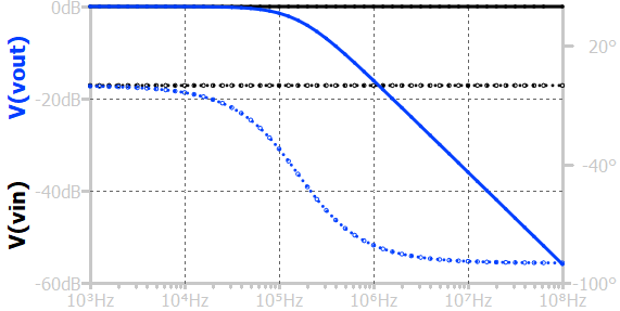
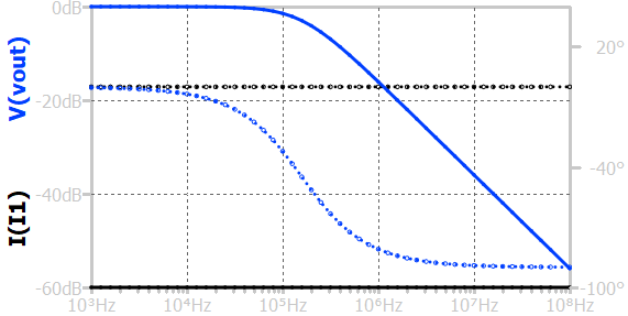
The above figure represents the frequency response of the RC low pass circuit. At low frequencies, the capacitor's reactance is large, causing minimal attenuation; thus, the output amplitude is nearly equal to the input, and the phase shift is close to zero. As the input frequency increases, the capacitive reactance decreases, reducing the voltage at the output.
The frequency at which the output amplitude falls to \(1/\sqrt{2}\) (about 0.707) of the input amplitude is called the cutoff frequency, given by \(f_c = \frac{1}{2\pi RC}\). Beyond this frequency, the output amplitude decreases at a rate of 20 dB per decade, and the phase shift approaches –90°, indicating that the output lags the input. This behavior highlights the filter’s ability to pass low-frequency signals while attenuating higher-frequency components.
Steady-state sinusoid response
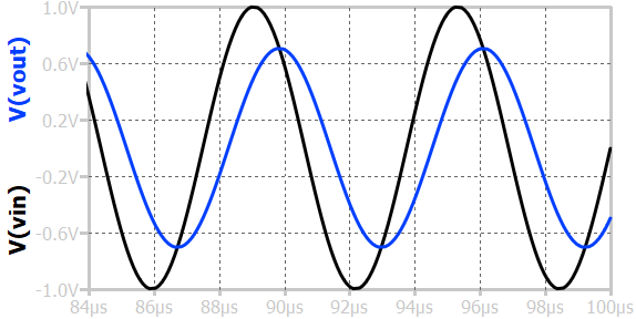
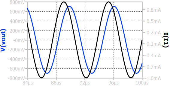
When a sinusoidal input voltage is applied to a first-order RC low-pass circuit, the output voltage is also sinusoidal but with reduced amplitude and a phase shift (delayed) relative to the input. The reduction of amplitude can be calculated using the frequency response plot.
Series RC circuit forming a high pass filter
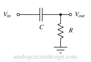
Step response
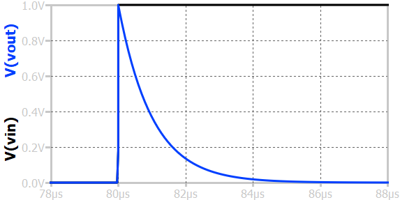
When a step input voltage is applied to a first-order RC high-pass circuit, the output voltage initially responds with a sharp spike (as shown in above figure) and then gradually decays to zero. At the moment the step is applied, the capacitor initially behaves like a short circuit, allowing the sudden change in voltage to appear almost entirely across the resistor, producing a high initial output. As time progresses, the capacitor begins to charge, opposing further changes in voltage, and the output voltage across the resistor decreases exponentially according to \(v_o(t) = V_{in} e^{-t/RC}\). After a long time, when the capacitor is fully charged, no current flows through the circuit, and the output voltage becomes zero. This transient response shows that the RC high-pass circuit effectively transmits rapid changes or high-frequency components of the input signal while rejecting slow or steady (low-frequency) variations.
Frequency response
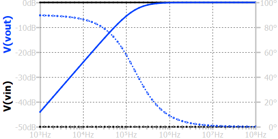
The above figure shows the frequency response of RC high pass circuit. At very low frequencies, the capacitor’s reactance is high, blocking most of the signal and resulting in a small output amplitude. As the frequency increases, the capacitive reactance decreases, allowing more of the input signal to pass through the resistor, and the output amplitude increases. The frequency at which the output amplitude reaches \(1/\sqrt{2}\) of the input amplitude is called the cutoff frequency, given by \(f_c = \frac{1}{2\pi RC}\). Above this frequency, the circuit allows signals to pass with little attenuation, while below it, signals are increasingly attenuated. The magnitude increases at rate higher than +20dB/dec below frequencies much lesser than the cutoff frequency. The phase shift of the output signal changes from +90° at low frequencies to 0° at very high frequencies, indicating that the output leads the input at low frequencies and becomes nearly in phase at high frequencies.
Steady-state sinusoid response
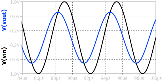
When a sinusoidal input voltage is applied to a first-order RC high-pass circuit, the output is also sinusoidal but with frequency-dependent amplitude and phase shift (phase-lead). At low frequencies, the capacitor’s reactance is high, limiting current flow and resulting in a small output voltage; the output lags the input by nearly 90°. As the frequency increases, the capacitive behaves like a short, allowing more signal to appear across the resistor, and the output amplitude approaches the input amplitude. At frequencies much higher than the cutoff frequency \(f_c = \frac{1}{2\pi{}RC}\), the output nearly equals the input in amplitude, and the phase shift approaches 0°, meaning the output and input are almost in phase.
Parallel RC circuit

Step response
When a step input current is applied to a first-order RC low-pass circuit, the output voltage across the capacitor does not change instantaneously but gradually rises toward the final steady-state value. Initially, the capacitor behaves like a short circuit, and the output voltage is zero. As time progresses, the capacitor charges, and the output voltage increases exponentially.
Frequency response
The above figure represents the frequency response of the parallel RC circuit. The input is an AC current source providing 1A of linear current. At low frequencies, the capacitor's reactance is large, causing minimal attenuation; thus, the output amplitude is highest which is I×R, and the phase shift is close to zero. As the input frequency increases, the capacitive reactance decreases, reducing the voltage at the output.
The frequency at which the output amplitude falls to \(1/\sqrt{2}\) (about 0.707) of the input amplitude is called the cutoff frequency, given by \(f_c = \frac{1}{2\pi{}RC}\). Beyond this frequency, the output amplitude decreases at a rate of 20-dB/decade, and the phase shift approaches –90°, indicating that the output lags the input.
Steady-state sinusoid response
When a sinusoidal input current of amplitude 1A is applied to a first-order RC low-pass circuit, the output voltage (I×R) is also sinusoidal but with reduced amplitude and a phase shift relative to the input current. The reduction of amplitude can be calculated using the frequency response plot.
RC circuits have various applications in electronics, such as signal filtering, timing circuits, smoothing power supply voltages, and many other analog electronic systems. The behavior of an RC circuit depends significantly on the values of the resistor and capacitor and their arrangement within the circuit.