RF Basics
RF stands for Radio Frequency and refers to electromagnetic waves in the frequency range of approximately 30 MHz to 300 GHz. Primary applications are communication, weather monitoring, radar imaging etc. RF integrated circuits and modules are found in mobile phones, satellites, personal electronics (bluetooth devices), and Wi-Fi, radars, automobiles, satellites etc. Electromagnetic waves are transverse waves and it does not need medium to propagate. It can propagate through air or space.
Electromagnetic spectrum
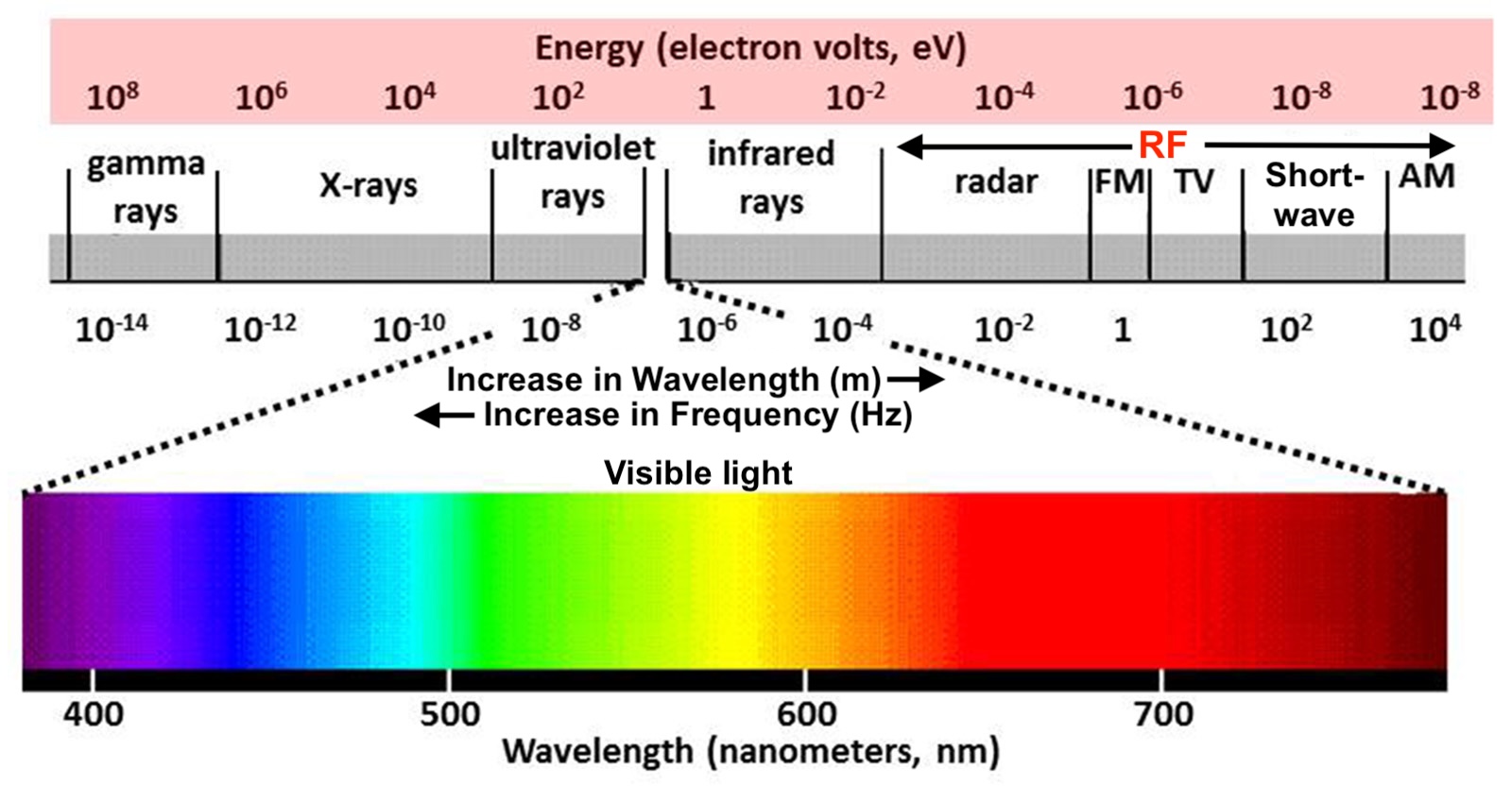
The electromagnetic spectrum is the complete range of electromagnetic radiation, spanning from low-frequency radio waves to high-energy gamma rays. It includes radio waves, microwaves, infrared, visible light, ultraviolet, X-rays, and gamma rays, all traveling at the speed of light. The RF (radio frequency) spectrum is a subset of the electromagnetic spectrum, typically ranging from a few MHz to several GHz. Understanding the RF spectrum of the application is essential for efficient spectrum allocation, interference control, and modern communication system design.
Fundamental Electromagnetic Wave Properties
Frequency and Period
Frequency: The number of complete cycles passed by an electromagnetic wave per second is called frequency. The units of measurement is Hz. Period: Time taken by the wave to complete one full cycle of oscillation. It is inverse of frequency and the unit of measurement is seconds. It tells how long a wave takes to return to the same value.
Wavelength
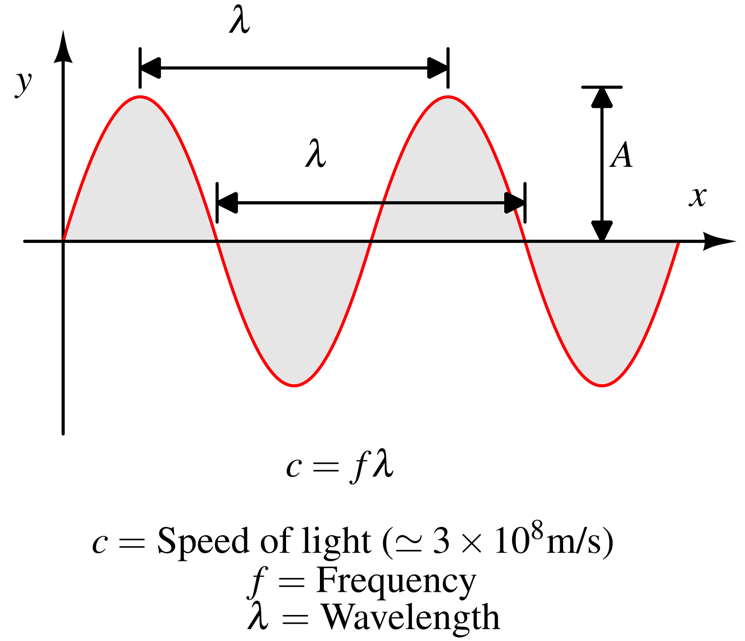
The physical distance between two consecutive peaks of a wave. It is represented by symbol λ. The units of measurement is m(meters). The relation between wavelength, speed and frequency is shown below : $$\text{Speed of wave}=\text{Frequency}\times{}\text{Wavelength}$$
Amplitude
It is the maximum displacement of the wave from its mean (equilibrium) position. It is denoted by A is the above diagram. It represents the energy of the wave, higher amplitude corresponds to higher energy. For an electromagnetic wave, the unit of amplitude of electric-field wave is V/m and magnetic field wave is H.
Phase
It is the position of a point in time on a waveform cycle, measured in degrees or radians.
Wavelength Calculation
Let’s calculate the wavelength for a Bluetooth signal at 2.4 GHz. Given frequency (f) = 2.4 GHz = 2.4 × 10⁹ Hz and speed of light (c) = 3 x 10⁸ m/s. Using the relationship c=fλ, we can obtain wavelength: $$\lambda{}=\cfrac{c}{f}=\cfrac{3\times{}10^8}{2.4\times{}10^9}=0.125\,\text{m}=12.5\,\text{cm}$$
Wireless communication
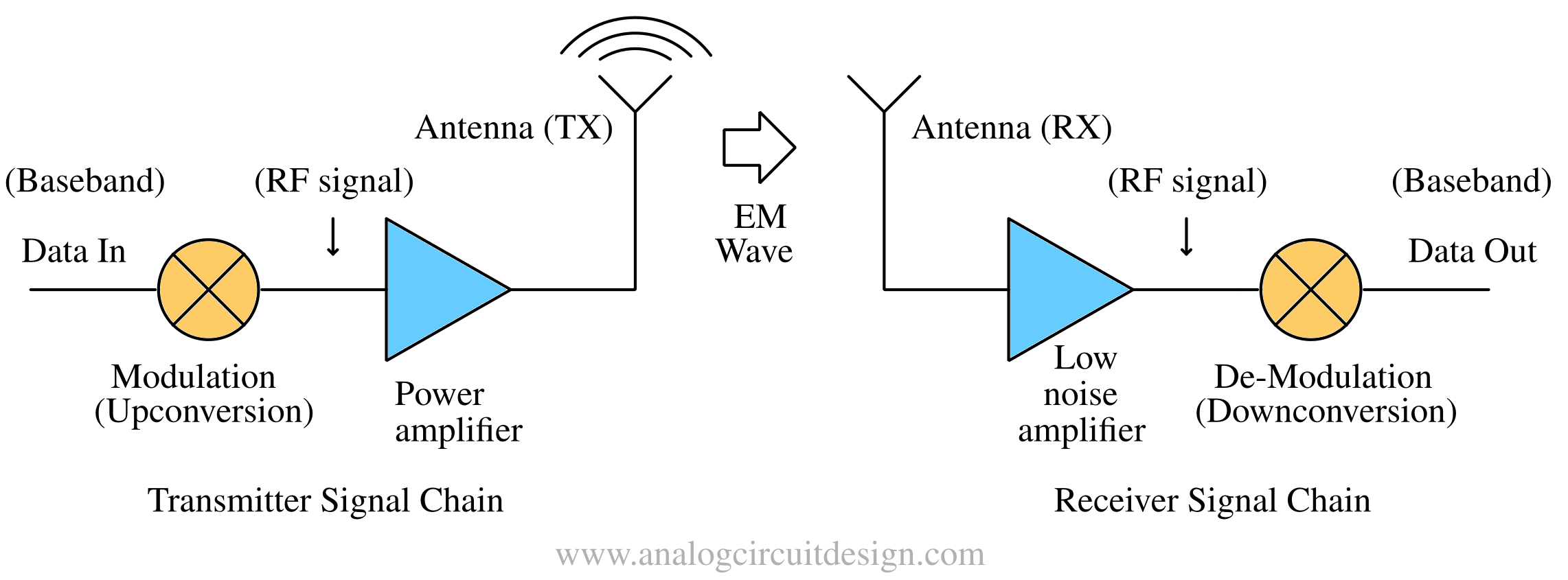
In wireless transmission, we usually want to transmit data via a transmitter (TX) and a connected antenna to a receiver (RX) using an electromagnetic (EM) wave through air or space as the medium. This arrangement is shown in figure below:
Unfortunately, wireless transmission is challenging. Some challenges :
- The wireless channel is shared among all users, making it a scarce and expensive resource. As a result, numerous regulatory requirements must be followed.
- The wireless channel has significant losses due to medium and distance resulting is attenuation.
- Unlike wired channels, wireless channel is time-varying because the transmitter and/or receiver may move, and the surrounding environment can also change due weather conditions.
Basic RF Terms
Radio Frequency (RF)
An electromagnetic wave with a frequency above 30 MHz is classified as RF. Such frequencies are easier to transmit through air or space because they allow the use of antennas of practical size.
Carrier Signal
It’s a high-frequency signal that “carries” the lower bandwidth of “real” information signals such voice and data. Messages are transmitted on high-frequency carrier waves because their shorter wavelengths enable the use of smaller antennas. This is done using a technique called modulation. In antenna theory, the effective area of antenna is proportional to square of wavelength (λ) of the signal1:
$$A_{e}=\cfrac{\lambda{}^2}{4\pi{}}G_0$$
Here, Ae is the effective area of the antenna, G0 is the gain (or directivity) of antenna at 0° angle. We can see that for a fixed gain, area of the antenna is directly proportional to wavelength. It means that to achieve smaller antenna, we have to use shorter wavelength (high-frequency) wave. For an isotropic antenna (a theoretical construct where the radiation is equal in all directions) Ae = λ2, while for a λ/2-dipole Ae = 0.13λ2.
| Application | Carrier Frequency | Characteristics |
|---|---|---|
| AM Radio | 535 kHz – 1605 kHz | Long range, follows Earth's curve |
| FM Radio | 88 MHz – 108 MHz | High fidelity, short range (line-of-sight) |
| 4G LTE / 5G (Low-band) | 600 MHz – 2.6 GHz | Excellent building penetration and coverage |
| Wi-Fi / Bluetooth | 2.4 GHz & 5 GHz | High data rates, very short range |
| 5G mmWave | 24 GHz – 53 GHz | Blazing speeds, blocked by walls/trees |
Baseband Signal
It is a low-bandwidth analog signal that carries information such as voice or data. It is found after the down-conversion (or demodulation) and before the analog-to-digital converter (ADC) in a radio receiver. Also, it is found immediately after the digital-to-analog converter (DAC) and before up-conversion (modulation) in a radio transmitter.
Modulation
Modulation is the process of encoding information (like voice, data, or video) onto a high-frequency carrier wave (like a radio wave) by varying a property of that wave (amplitude, frequency, or phase) to allow it to travel through air or space via electromagnetic wave.
More details about modulation : Modulation.
Power and Measurement
RF signals vary across massive ranges, so logarithmic scales are the industry standard.
Decibel (dB)
A logarithmic unit used to express the ratio between two quantities, typically power or voltage. Since wireless signal levels can span a very wide range—from high transmitter powers to extremely small received powers—using a linear scale in watts would involve many zeros after decimal and frequent unit conversions (e.g., W to mW or µW), making it in-convenient.
dBm
Power in Decibel relative to 1 milliwatt. This is the standard unit for measuring signal strength in Wireless RF domain (e.g., 0 dBm = 1mW, 10mW = 10dBm). The formula : $$\text{P (dBm)}=10\times{}\log_{10}\left(\cfrac{P (W)}{1\,\text{mW}}\right)$$ -110dBm = 10-11mW = 0.00001 nW Here, P (W) is power in Watt, and P (dBm) is power in dBm. Note that for power, the multiplication factor is 10 in the formula because units involved are of power (W or V2). For measurements involving voltage (V), the multiplication factor is 20.
dBc
It stands for decibels relative to the carrier. It is a relative unit used to measure the power of a signal (like noise, harmonics, or spurs) in relation to the main carrier signal power. Unlike dBm, which is an absolute measure of power relative to 1 milliwatt, dBc is purely comparative.
Attenuation
The loss of signal strength as it travels through a medium (cables, air, or walls). It is also measured in Decibels (dB) due to huge range of values. The formula is : $$\text{Attenuation (W/W)}=\cfrac{P_T}{P_R}$$ $$\text{Attenuation (dB)}=P_T(\text{dBm})-P_R(\text{dBm})$$
Gain
The increase in signal power, usually provided by an amplifier or a directional antenna. It is also measured in Decibels (dB) due to huge range of values. It is the inverse of attenuation. It is expressed as: $$\text{Gain (W/W)}=\cfrac{P_R}{P_T}$$
Example of attenuation, Transmit and Receive power in dBm
Consider the following example of Bluetooth device. The transmit power is 1W, frequency is 2.4 GHz, communication distance is 100m and using λ/2 dipoles on both ends :
Transmit power in dBm - $$P_T(dBm)=10\log_{10}\left(\cfrac{1W}{1mW}\right)=30\,\text{dBm}$$ Using PR equation mentioned above, $$P_R=P_T\cfrac{0.13\lambda{}^2\cdot{}0.13\lambda{}^2}{d^2\lambda{}^2}=P_T\cdot{}0.13^2\left(\cfrac{\lambda{}}{d}\right)^2=26\,\text{nW}=-45.78\,\text{dBm}$$ The received power is -45 dBm and transmit power is 30 dBm. Therefore, the attenuation is PT(dBm)-PR(dBm)=75dB
75dB is a big number, it means that the power has dropped by 31 million times !
Power to voltage conversion
To convert power into voltage, we have to know the load resistance. In RF systems, the most common resistance is 50 Ω. The formula is :
$$P=\cfrac{V_p^2}{2R}$$
If power of -110dBm is applied across a 50 Ω resistor, it produces amplitude of 0.7μV which is not much and could be buried under noise.
RF communication systems
Simplex system
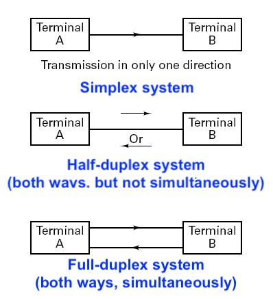
A simplex system is a mode of operation where data flows in only one direction. One device acts strictly as the transmitter, while others act strictly as receivers, with no capability for the receiver to respond on the same channel. Remote central locking in cars have simplex RF system. It is highly reliable for one-way delivery since there is no risk of signal collision or channel competition.
Half duplex system
A half-duplex system allows bidirectional data flow between devices, but not simultaneously. Both devices can transmit and receive, but they must take turns on the same channel or frequency. Systems must alternate between transmit (TX) and receive (RX) modes. This often involves a "line turnaround time," which is the delay required for the hardware to switch roles. Unlike full-duplex systems that use two separate frequencies, half-duplex uses one frequency for both directions, making it more spectrum-efficient for low-bandwidth needs.
Examples of Half-Duplex systems :
- Wifi and Bluetooth : While they appear simultaneous to the user, they actually switch between transmitting and receiving very rapidly (fast TX/RX switching) at physical level. The speed is so high (>50 mbps), we don't realize that it is a half-duplex system while on a video call.
Full duplex system
A full-duplex system allows for simultaneous bidirectional data flow. Unlike simplex (one-way) or half-duplex (taking turns), full-duplex devices can transmit and receive signals at the exact same time. Common techniques to achieve full-duplex
Examples of Full-Duplex systems :
- Cellular phones
- Satellite communication
Basic building block of an RF system
An RF (Radio Frequency) system is built from a set of specialized components that work together to translate data into electromagnetic waves and back again. These building blocks are typically categorized into the Transmitter (TX) and Receiver (RX) chains.
RF integrated circuit or module
- Transmitter : Digital to analog converter (DAC), Mixer (I-Q modulator), Power amplifier, Local oscillator (VCO + PLL), Crystal (highly stable reference frequency) etc.
- Reciever : LNA (low noise amplifier), mixer (I-Q demodulator), Intermediate frequency amplifier, filters, Analog to digital converter (ADC)
Balun
A balun (balanced to unbalanced) is an electrical device that converts a balanced signal (fully differential outputs) to unbalanced signal (single-ended signal). Example : In transmitter, output of mixer is usually fully differential, it is converted to single ended using Balun before connecting to power amplifier. In receivers, it is used to convert single ended (unbalanced) signal from LNA to a balanced signal to processed by the down-converting mixer.
Matching networks
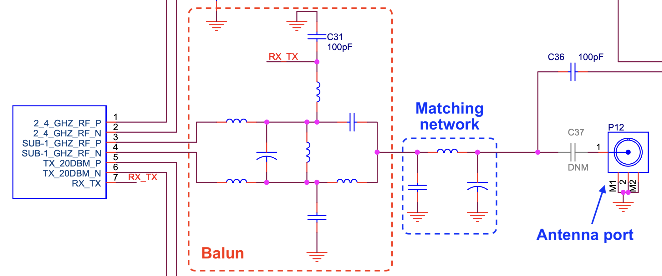
A matching network, also known as an impedance transformer, is used to achieve impedance matching between a source and a load, such as between a power amplifier and an antenna. It is done to achieve maximum power transfer and avoid reflections. Reflections may cause excessive voltage (when open) or current (when short).
Filters
Filters help reduce noise (which improves sensitivity), suppress interferers, limit bandwidth to meet regulatory requirements, and select the desired channel. Typically, low-pass filters and high-Q bandpass filters are used.

Antenna
The antenna is the "transducer" that converts the electrical signals traveling through wires (guided waves) into electromagnetic waves traveling through free space (unguided waves) or vice-versa. In transmitters, it is the final component. In receivers, it is the first component of the signal chain.
Phase noise of transmitter
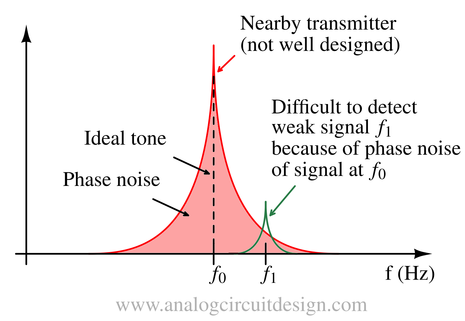
Phase noise is a key parameter for transceivers. As shown in the above figure, the phase noise of local oscillators (at frequency f0) is making hard to detect the desired signal (at frequency f1).
Transmission and Received power
In order to estimate the recieved power (PR) of the wireless transmission at the receiver we can use Friis’ transmission formula2 :
$$P_R=P_T\cfrac{G_TG_R\lambda{}^2}{(4\pi{})^2d^2}$$
Here, PR is the received power and PT is the transmit power. GR (and GT) is the receive/transmit antenna gain, while d is the distance between the two antennas.
Having higher received power ensures higher SNR for better sensitivity.
There is another form of the above formula :
$$P_r=P_t+G_t+G_r+20\log_{10}\left(\cfrac{\lambda{}}{4\pi{}}\right)-20\log_{10}(d)$$
Here, PR and PT are the received power and transmit power in dBm. GR (and GT) is the receive/transmit antenna gain in dB, while d is the distance between the two antennas. λ is the wavelength of signal in meters.
Free-Space Path Loss (FSPL)
The electromagnetic waves loses strength because it moves radially outwards in the space. The loss can be quantified using free space path loss (FSPL) formula. For a clear line-of-sight link in free space, the free-space path loss is (assuming no multi-path fading, ideal antennas etc):
$$\text{FSPL}=\left(\cfrac{4\pi{}d}{\lambda{}}\right)^2=\left(\cfrac{4\pi{}df}{c}\right)^2$$
or the above equation can be represented in dB as :
$$\text{FSPL(dB)}=32.44+20\log_{10}(f_{\text{MHz}})+20\log_{10}(d_{\text{km}})$$
Following things can be observed from the above equations :
- Double the frequency, half the range (433 MHz can provide longer range than 868 MHz)
- 6 dB improvement means twice the distance
Range of RF system
To extend the range of RF systems, following measures can be taken:
- Increase the Output power (Add an external power amplifier, PA)
- Increase the sensitivity (Add an external low noise amplifier, LNA)
- Use high gain antennas
RF applications and operating frequencies
| Application | Frequency | Wavelength | Antenna Size (λ/2 dipole) |
|---|---|---|---|
| FM radio | 88-108 MHz | 2.8-3.4 m | 75 cm |
| Bluetooth | 2.4 GHz | 12.5 cm | 3.1 cm |
| Wifi (lowband) | 2.4 GHz | 12.5 cm | 3.1 cm |
| Wifi (highband) | 5 GHz | 6 cm | 1.5 cm |
| GSM (cellular) | 900 MHz | 33 cm | 8.25 cm |
| GNSS (GPS) | 1.575 GHz | 19 cm | 4.75 cm |
Radar Frequency Nomenclature
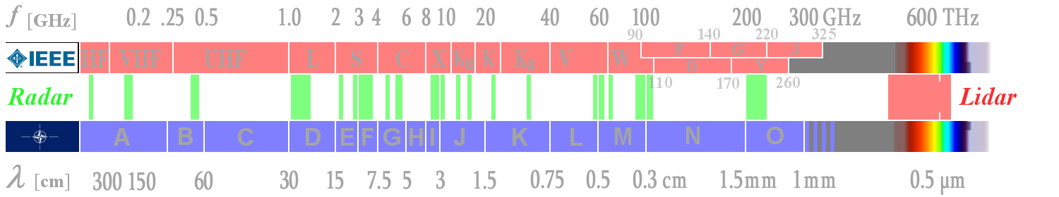
Radar Frequency Ranges. (Source : radartutorial.eu)
Satellite Frequency Nomenclature
| Band | Downlink Frequency (GHz) | Uplink Frequency (GHz) | Typical Bandwidth (MHz) | Notes |
|---|---|---|---|---|
| L | 0.9 to 1.6 | 0.9 to 1.6 | 15 | Terrestrial - shared |
| S | 1.61 to 1.63 | 2.48 to 2.50 | 70 | ISM-band - shared |
| C | 3.7 to 4.2 | 5.925 to 6.425 | 500 | Terrestrial - shared |
| X | 7.25 to 7.75 | 7.9 to 8.4 | 500 | Military / Government |
| Ku | 11.75 to 12.2 | 14.0 to 14.5 | 500 | Rain attenuation |
| Ka | 17.7 to 21.2 | 27.5 to 31.0 | 3500 | Rain attenuation |
-
Constantine A. Balanis, ANTENNA THEORY ANALYSIS AND DESIGN, Third Edition. ↩
-
D. M. Pozar, Microwave Engineering. Wiley, 2011. ↩
-
K. S. Kundert, "Introduction to RF simulation and its application," in IEEE Journal of Solid-State Circuits, vol. 34, no. 9, pp. 1298-1319, Sept. 1999, doi: 10.1109/4.782091. ↩