S-Parameters Basics
S-parameters, or scattering parameters, often represented in an S-matrix, are essential for the characterization and design of n-port distributed networks like complex RF circuit components (LNA, directional couplers) and transmission lines. S-parameters can be measured using vector network analyzers (VNA).
Definition of the scattering parameters
Two port network and N-port network are common in s-parameter analysis.
Two port network
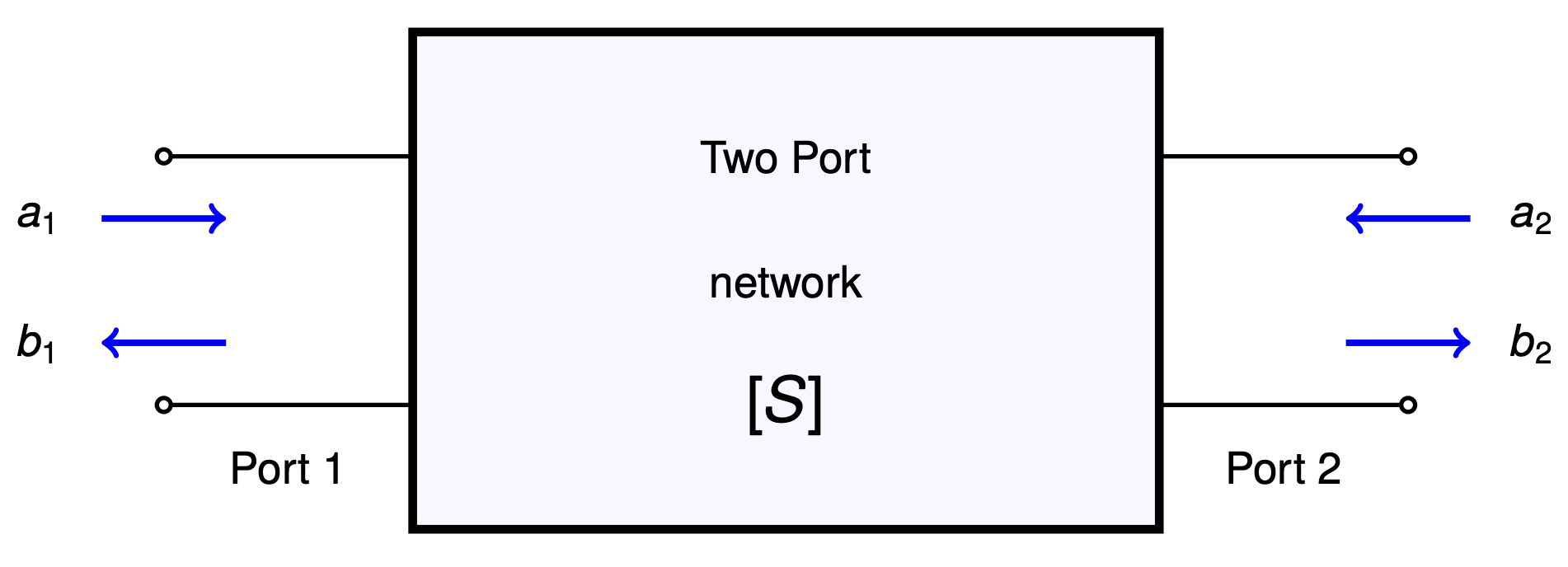
$$b_1=s_{11}a_1+s_{12}a_2$$ $$b_2=s_{21}a_1+s_{22}a_2$$
or using matrix notation,
$$\begin{bmatrix}b_1 \\ b_2\end{bmatrix}=\begin{bmatrix}s_{11} & s_{12} \\ s_{21} & s_{22}\end{bmatrix}\begin{bmatrix}a_1 \\ a_2\end{bmatrix}$$
a is the incident wave vector and b is the reflected wave vector.
$$S_{11}=\cfrac{b_1}{a_1}\Big|_{a_2=0}$$
When s11 is being measured, the port-2 (output) should be matched such that there is no reflection (a2 equal to zero). s11 signifies the reflection from port-1. In LNAs or PAs, s11 should be ideally zero. Practically, less than -10dB is considered good.
$$S_{12}=\cfrac{b_1}{a_2}\Big|_{a_1=0}$$
When s12 is being measured, the port-1 (input) should be matched such that there is no reflection (a1 equal to zero). s12 signifies transfer function from output port to input port. If a disturbance is made at the output port, s12 tells how much of it appears at the input port. In LNAs or PAs, s12 should be ideally zero. Practically, less than -40dB is considered good.
$$S_{21}=\cfrac{b_2}{a_1}\Big|_{a_2=0}$$
When s21 is being measured, the port-2 (output) should be matched such that there is no reflection (a2 equal to zero). s21 signifies transfer function from input port to output port. If a signal is applied at the input port, how much of it appears at the output port. In LNAs s21 should be as high as possible. Practically, greater than +10dB is considered good.
$$S_{22}=\cfrac{b_2}{a_2}\Big|_{a_1=0}$$
When s22 is being measured, the port-1 (input) should be matched such that there is no reflection (a1 equal to zero). s22 signifies output port's reflection performance. If a signal is applied at the output port, s22 tells how much of it is reflected back to the output port. In LNAs s21 should be zero. Practically, lower than -10dB is considered good.
N-port network
In the general case, for any network with N-ports, the incident and reflected wave can be expressed as nth order column vectors [a] and [b]. This results in NxN s-parameter matrix as shown below:
$$\begin{bmatrix}b_1 \\ b_2 \\ \vdots{} \\ b_n\end{bmatrix}=\begin{bmatrix}s_{11} & s_{12} & \dots{} & s_{1n}\\s_{21} & s_{22} & \dots{} & s_{2n} \\ \vdots{} & \vdots{} & \vdots{} & \vdots{} \\ s_{n1} & s_{n2} & \dots{} & s_{nn}\end{bmatrix}\begin{bmatrix}a_1 \\ a_2 \\ \vdots{} \\ a_n\end{bmatrix}$$
Why S-parameters ?
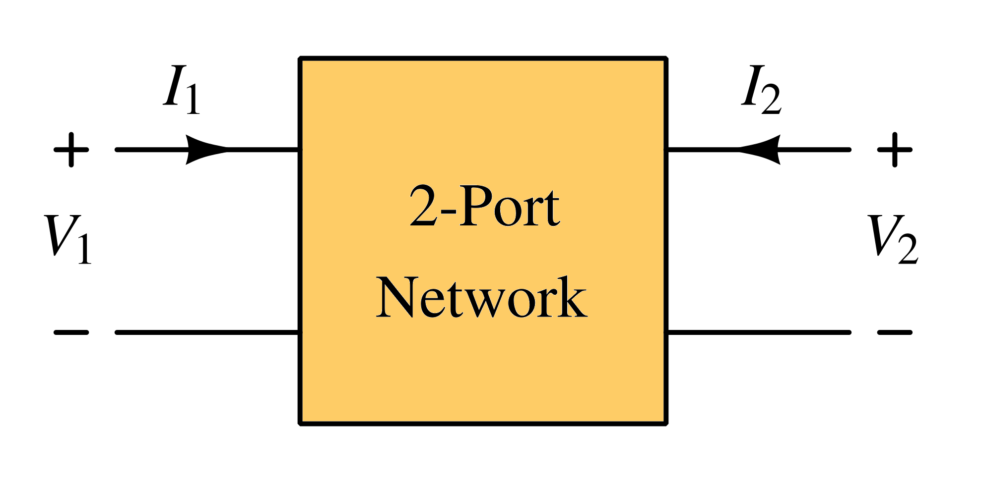
A two-port network as shown above can be characterized using several parameter sets, such as H (hybrid), Y (admittance), and Z (impedance) parameters. These parameter sets relate the total voltages and currents at each of the two ports, which are referred to as the network variables. Let's consider Z-parameter as an example to see why at GHz frequency z-parameter may not be suitable:
Z-parameters $$V_1=z_{11}I_1+z_{12}I_2$$ $$V_2=z_{21}I_1+z_{22}I_2$$
We can measure Z11 with a test current into port-1 and measure the voltage across port-1 while open circuit on port-2 (I2=0). At GHz frequencies, open circuit has parasitic capacitances and voltage reflections.
At GHz range frequency, things cannot be considered lumped anymore because of distributed nature of transmission lines. The voltages act like travelling wave and varies with time and distance along the transmission like. There are following sources of inaccuracies in Z, Y and H parameter representation:
- Its hard to measure total voltage and total current at the ports of the network because of reflections.
- Short and open circuits are difficult to realize over a wide range of frequencies. Shorts have parasitic inductances while open have parasitic capacitances.
- Active devices, such as transistors and tunnel diodes, are often not stable when terminated with a short circuit or an open circuit.
Therefore, rather than using total voltage and current as independent variables, traveling waves are used to represent voltages and currents at different points along a transmission line. Travelling wave voltage depend not only on the time but position of the transmission line. It is represented as sum of incident and reflected wave.
Transmission lines basics
At high frequencies, where the wavelength is comparable to the length of the transmission line, voltage propagates as a wave. As a result, the voltage can vary along the line. To capture this behavior, the following model is used:
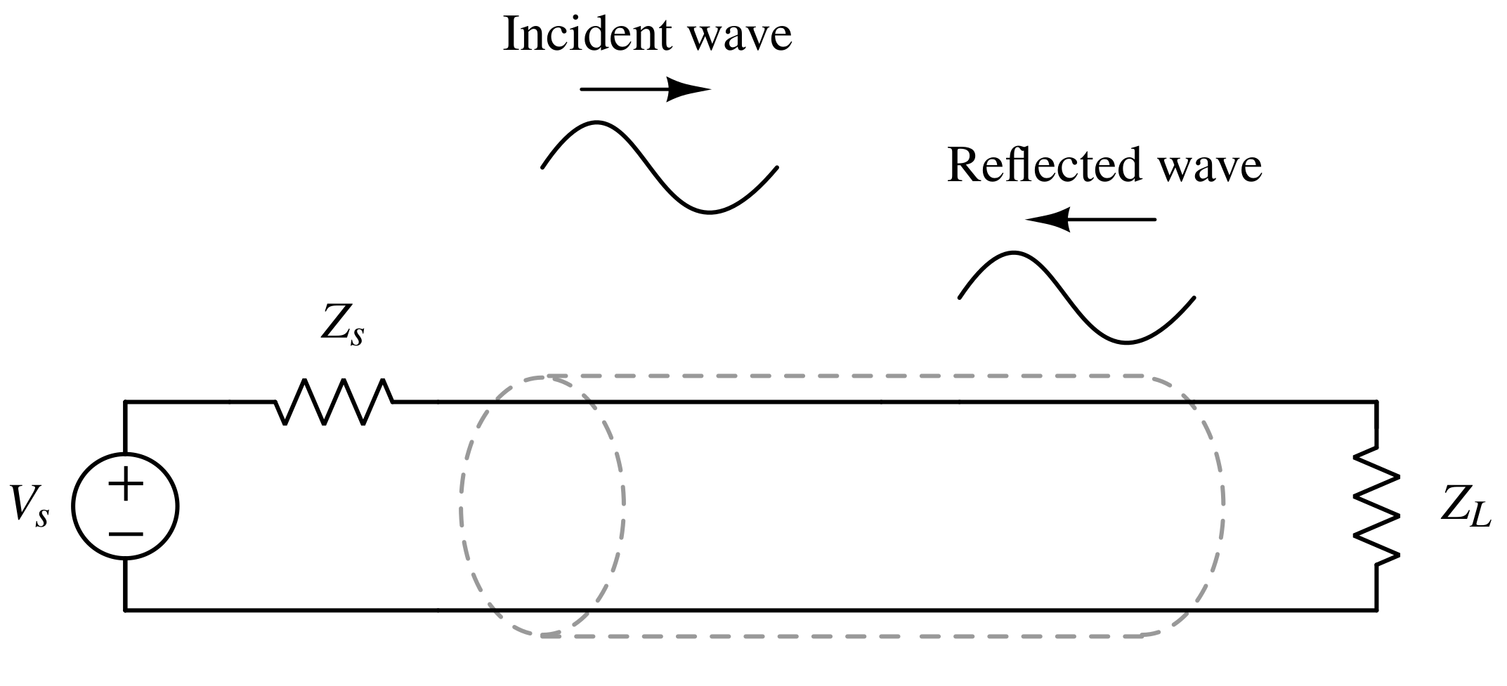
A portion of the waves incident on the load will be reflected. It then becomes incident on the source, and in turn re-reflects from the source (if ZS not equal to Zo), resulting in a standing wave on the transmission line.
A small section of a transmission line can be modeled as follows :
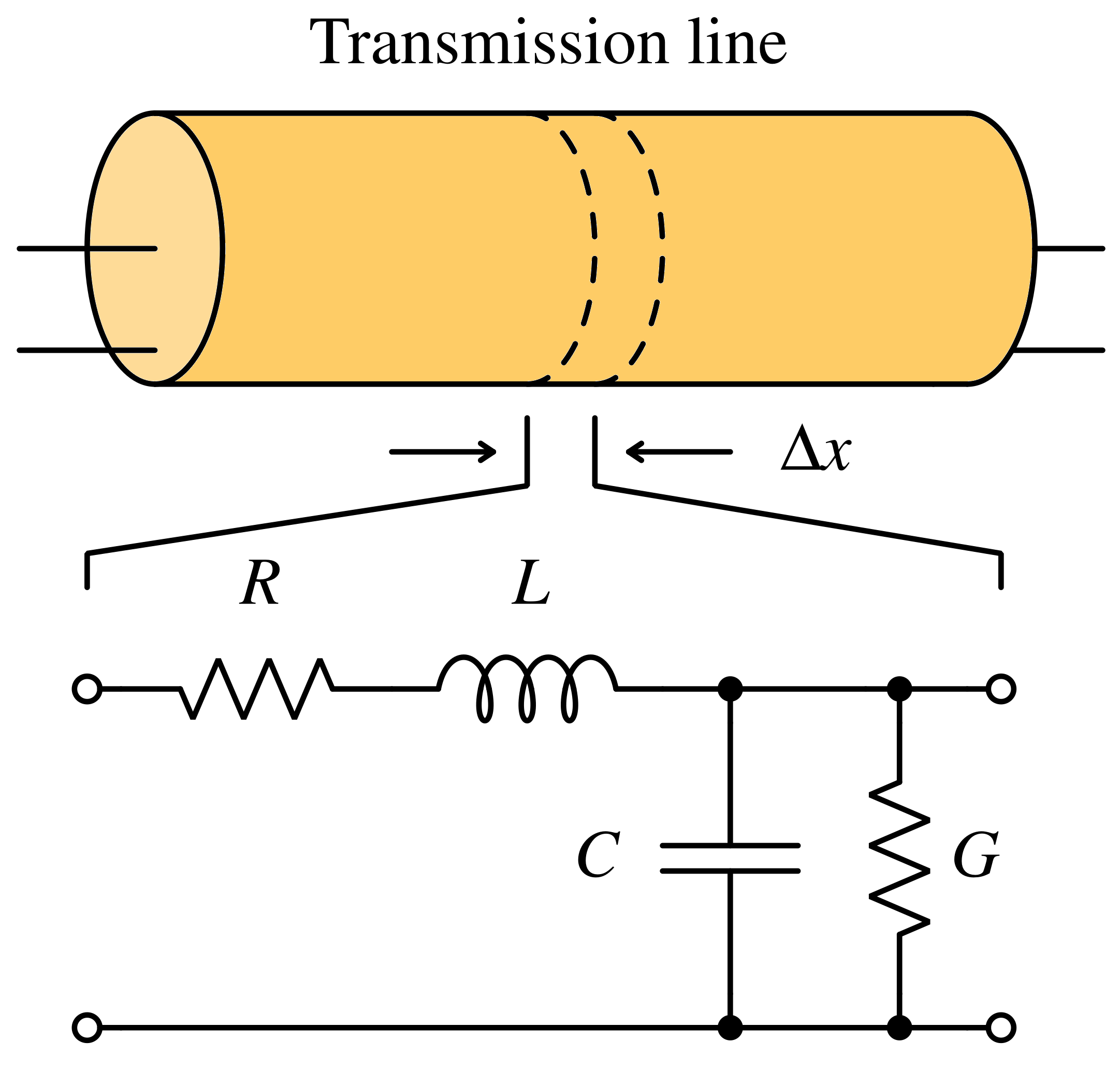
A lossless line means R = 0 and G = ∞. The characteristic impedance of a lossless line is Z0:
$$Z_0=\sqrt{\cfrac{L}{C}}$$
Most microwave transmission lines are designed to have Z0 of 50 Ω
Total voltage
The Total Voltage (Vt) at any point along the transmission line is equal to the sum of the incident and reflected waves at that location.
$$V_t=V_{inc}+V_{ref}$$
Here, Vinc is the incident wave, Vref is the reflected wave. In Z, H and Y parameters we deal with total voltages.
Total current
The Total Current (It) on the transmission line is obtained by taking the difference between the incident and reflected voltage waves and dividing it by the line’s characteristic impedance.
$$I_t=\cfrac{V_{inc}-V_{ref}}{Z_0}$$
In Z, H and Y parameters we deal with total currents.
Reflection coefficient
The reflection coefficient is a measure of how much of an incident wave is reflected when it encounters an impedance discontinuity, such as a load connected to a transmission line. It is defined as the ratio of the reflected wave amplitude to the incident wave amplitude
$$\Gamma{}=\cfrac{V_{ref}}{V_{inc}}=\rho{}\angle{}\theta{}=\cfrac{Z_L-Z_0}{Z_L+Z_0}$$
The reflection coefficient can be made equal to zero by selecting a load, ZL, equal to the characteristic impedance of the line
Relation between Reflection coefficient and s-parameters
In the general case of a two-port network where S12≠0 and S21≠0, the input reflection coefficient Γin will be dependent on the value of the load and vice versa. To derive the input reflection coefficient of the two-port, Γin with ΓL terminating port 2, let's apply the definition of reflection coefficient at the output port:
$$\Gamma{}_L=\cfrac{V_{ref}}{V_{inc}}=\cfrac{b_2}{a_2}$$
Substituting the above relation into the following relationship:
$$b_2=s_{21}a_1+s_{22}a_2$$
we get,
$$b_2=s_{21}a_1+s_{22}b_2\Gamma{}_L$$
$$\implies{}b_2=\cfrac{s_{21}a_1}{1-s_{22}\Gamma{}_L}$$
other equation is :
$$b_1=s_{11}a_1+s_{12}a_2$$
Substituting below mentioned equation into above equation:
$$\Gamma{}_{in}=\cfrac{V_{ref}}{V_{inc}}=\cfrac{b_1}{a_1}$$
we get,
$$\Gamma{}_{in}=s_{11}+s_{12}\cfrac{a_2}{a_1}$$
or,
$$\Gamma{}_{in}=s_{11}+s_{12}\cfrac{b_2\Gamma{}_L}{a_1}$$
Substituting the value of b2 we derived earlier in terms of Γ, we get:
$$\Gamma{}_{in}=s_{11}+\cfrac{s_{21}s_{12}\Gamma{}_L}{1-s_{22}\Gamma{}_L}$$
VSWR
VSWR stands for "Voltage standing wave ratio". The relation between VSWR and reflection coefficient is:
$$\text{VSWR}=\cfrac{1-\Gamma{}}{1+\Gamma{}}$$
Reciprocal network
A reciprocal network is defined as having identical transmission characteristics from port one to port two or from port two to port one. This implies that the s-parameter matrix is equal to its transpose. In the case of a two port network, s12 = s21.
S parameter applications
S-parameters characterize the behavior of many electronic systems, including the following:
-
S-parameters are used to characterize and model transmission lines between various components, such as connectors, cables, and waveguides. S-parameters help engineers understand signal reflections, losses, and impedance matching, ensuring efficient energy transfer in high-frequency systems.
-
In antenna design, S-parameters help evaluate their impedance matching with the transmission line, understand how efficiently they radiate or receive electromagnetic waves and helps ensure desired radiation patterns.
-
Using S-parameters in amplifiers (Low noise amplifiers and Power amplifiers), engineers can determine gain, bandwidth, input/output impedance matching, and stability of amplifiers.
-
Filters—whether low-pass, high-pass, band-pass, or band-stop—can be analyzed using S-parameters to evaluate characteristics such as insertion loss, return loss, and bandwidth.