RL (resistor-inductor) circuit
An RL circuit, also known as a resistor-inductor circuit or RL network, comprises a combination of inductors and resistors and is commonly energized by a power source. It involves connecting an inductor and a resistor in either a parallel or series configuration. These circuits can be driven by either a current source (in parallel) or a voltage source (in series). Alongside capacitors (C) and resistors (R), inductors (L) constitute the fundamental passive linear circuit elements. Together, they can form electrical circuits in various configurations such as the RC circuit, LC circuit, and RLC circuit.
Alternatively, an RL circuit can be defined as an electrical circuit incorporating resistance and self-inductance. Induction occurs when an electromotive force (emf) source applies a continuous change in magnetic flux. Mutual inductance arises from Faraday's laws of induction, while self-inductance is an effect of Faraday's laws of induction on a device acting upon itself. The inductor, a component exhibiting self-inductance, plays a pivotal role in the circuit. However, due to the presence of a resistor in the ideal circuit, an RL circuit will dissipate energy, akin to an RC or RLC circuit.
Types of RL circuit
RL circuit depending on the way the resistor and inductor are connected can be classified in the following ways:
- Series RL circuit
- Parallel RL circuit
Series RL circuit forming low pass filter
A series RL circuit is a type of electrical circuit that contains a resistor (R) and an inductor (L) connected in series to a voltage source as shown in Fig 1 and 2. In this configuration, the current through all the components (R, L, and voltage source) is the same. The series RL circuit is powered by a voltage source (such as a battery or an AC power supply) that provides the electrical potential necessary for the circuit to operate.

If the output is taken across the resistor (as shown in Fig 1), the circuit's transfer function is a low-pass filter.
Frequency response
The transfer function of above RL circuit is :
$$\cfrac{v_{out}(\omega{})}{v_{in}(\omega{})}=\cfrac{R}{R+j\omega{}L}$$
Comparing it with low-pass transfer funciton:
$$\cfrac{v_{out}(\omega{})}{v_{in}(\omega{})}=\cfrac{A}{1+j\omega{}/\omega{}_c}$$
We obtain,
$$A=1$$
$$\omega{}_c=\cfrac{R}{L}$$
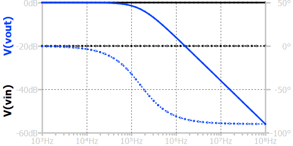
ωc is the -3dB point of the transfer function. It is also called the cutoff frequency. It is the frequency where the transfer function's gain falls by 3dB. At this frequency, the phase drops by 45°.
Step response
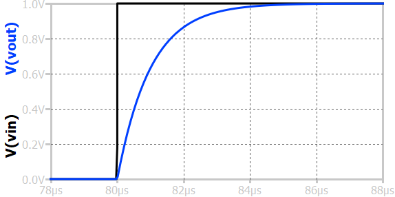
As shown above, when a step input voltage is applied to a first-order RL low-pass circuit, the output voltage across the inductor initially starts at zero and gradually rises to the final steady-state value. At the moment the step is applied, the inductor opposes sudden changes in current by developing a large induced voltage, acting like an open circuit. As time progresses, the current through the inductor increases exponentially, following the expression \(i(t) = \frac{V_{in}}{R}(1 - e^{-tR/L})\), and the output voltage across the inductor \(v_L(t)\) decreases exponentially as the magnetic field builds up. The time constant of the circuit, \(\tau = \frac{L}{R}\), determines how quickly the current and voltages reach steady state. After about five time constants, the current reaches its maximum value and the inductor behaves like a short circuit, causing the output voltage across it to become zero. This gradual change demonstrates the RL low-pass circuit’s ability to pass slowly varying signals while opposing rapid changes in the input.
Steady-state sinusoid response
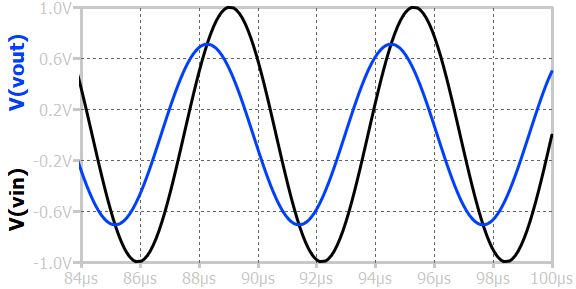
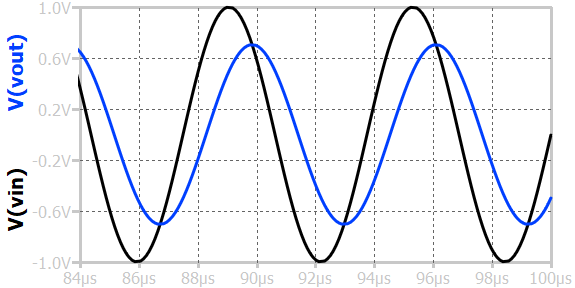
When a sinusoidal input voltage is applied to a first-order RL low-pass circuit, the output voltage across the inductor varies in amplitude and phase depending on the input frequency. At low frequencies, the inductive reactance \(X_L = 2\pi{}f_L\) is small, so the inductor offers little opposition to current flow, and most of the input voltage appears across it; thus, the output amplitude is nearly equal to the input. As the frequency increases, the inductive reactance increases, causing a larger portion of the input voltage to drop across the resistor and reducing the output amplitude across the inductor.
Series RL circuit forming high pass filter

If the output is taken across the inductor (as shown in Fig 2), the circuit's transfer function is a high-pass filter.
Frequency response
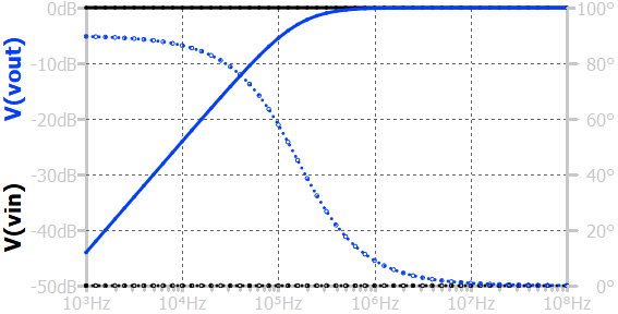
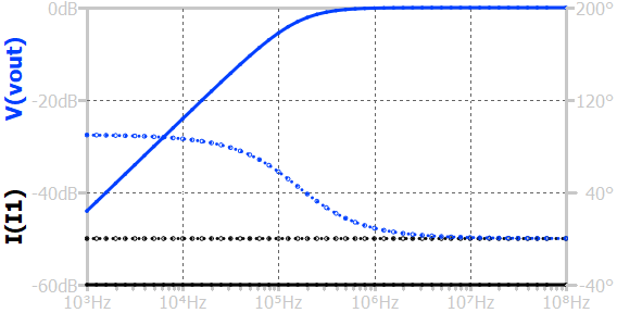
The frequency response (shown above) shows how the output amplitude and phase vary with the frequency of the input signal. At low frequencies, the inductive reactance \(X_L=2\pi{}f_L\) is small, causing most of the input voltage to appear across the inductor and very little across the resistor, resulting in a low output amplitude. As the frequency increases, \(X_L\) increases, forcing more voltage across the resistor and raising the output amplitude. The frequency at which the output voltage magnitude reaches \(\frac{1}{\sqrt{2}}\) (about 70.7%) of the input voltage is called the cutoff frequency, expressed as \(f_c=\frac{R}{2\pi{}L}\). Beyond this point, the circuit passes signals with little attenuation, while below it, the output drops at a rate of 20-dB per decade. The phase angle between the input and output transitions smoothly from +90° at very low frequencies to 0° at very high frequencies.
Steady-state sinusoid response
When a sinusoid input is applied, at low frequencies, the inductive reactance \(X_L=2\pi{}f_L\) is small, so most of the input voltage appears across the inductor, and the output across the resistor is very small. As the frequency increases, the inductive reactance becomes larger, causing more voltage to appear across the resistor, and the output amplitude increases. The frequency at which the output amplitude reaches \(\frac{1}{\sqrt{2}}\) (about 70.7%) of the input amplitude is called the cutoff frequency, given by \(f_c=\frac{R}{2\pi{}L}\). Above this frequency, the circuit allows signals to pass with minimal attenuation, while below it, signals are increasingly suppressed. The phase shift between input and output changes from 0° at high frequencies to +90° at low frequencies, indicating that the output leads the input at lower frequencies.
Step response
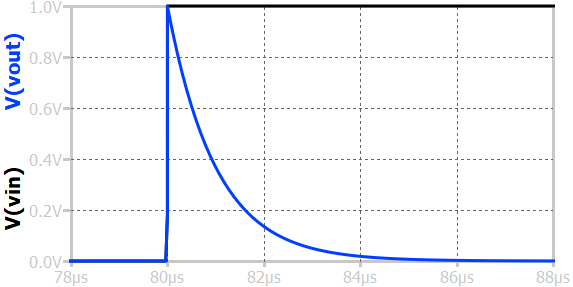
When a step input voltage is applied to a first-order RL high-pass circuit, the output voltage across the resistor initially rises sharply and then gradually decays to zero. At the instant the step is applied, the inductor opposes any sudden change in current, acting like an open circuit, resulting in zero voltage drop across resistor, producing a high initial output. As time progresses, the inductor current increases exponentially according to \(i(t)=\frac{V_{in}}{R}(1 - e^{-tR/L})\), causing the output voltage to decrease exponentially as \(v_o(t) = V_{in}e^{-tR/L}\). After a long time, when the current reaches its steady-state value, the inductor behaves like a short circuit, and the output voltage across the resistor becomes zero.
Parallel RL circuit

Frequency response
At low frequencies, the inductor’s reactance is high, so most of the input current flows through the resistor, producing a highest voltage (I×R) across the parallel combination. As the frequency increases, the inductor’s reactance drops, reducing the output voltage. The frequency at which the output voltage reaches \(\frac{1}{\sqrt{2}}\) (about 70.7%) of its maximum value is called the cutoff frequency, given by \(f_c=\frac{R}{2\pi{}L}\). Above this frequency, the circuit passes signals with little attenuation, while below it, the output voltage decreases at a rate of 20-dB/decade. The phase angle between the input current and output voltage transitions from +90° at low frequencies to 0° at high frequencies.
Step response
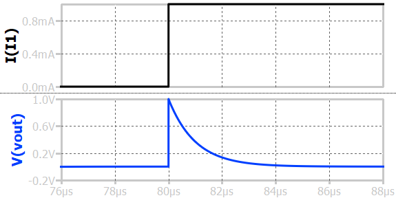
When a step current is applied to a first-order parallel RL circuit, the output voltage across the resistor-inductor combination rises instantly to I×R and then gradually approaches zero. At the moment the current step is applied (fast edge), the inductor acts like an open circuit, so most of the input current flows through the resistor, resulting in a highest initial voltage at the output (I×R). As time progresses, the current through the inductor increases exponentially, while the current through the resistor decreases, causing the voltage across the parallel combination to drop exponentially toward zero. The time constant of the circuit, \(\tau = L/R\), determines how quickly the voltage reaches its final value.
Steady-state sinusoid response
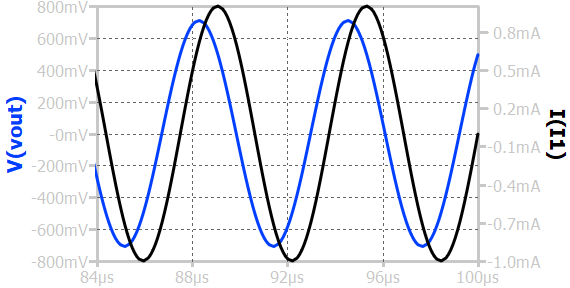
When a sinusoidal current is applied to a first-order parallel RL circuit, the output voltage across the resistor-inductor combination depends on the frequency of the input. At low frequencies, the inductor act as short, resulting in a low output voltage. As the frequency increases, the inductor’s reactance rises, diverting more current through the resistor and increasing the voltage across the parallel combination.