Self and mutual inductance
Self-inductance is the measurement of the tendency of a coil to resist changes in current in itself. Whenever current changes through a coil, it induces an opposite voltage. The magnitude of the voltage is proportional to the rate of change of current through the coil. The unit of self-inductance is Henry, abbreviated "H".
Working mechanism of self inductance
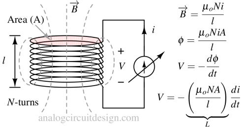
When a current flows through a conductor, it generates a magnetic field around it. The self-inductance of the conductor is a measure of how this magnetic field links with the conductor itself. When the current through the conductor changes, the magnetic field also changes. According to Faraday's law of electromagnetic induction, this change in magnetic flux induces a voltage in the conductor.

Mathematical representation of self inductance
This relationship is described by the following equation:


Where V is the induced voltage (in volts), L is the self-inductance of the conductor/coil (H), and di/dt is the rate of change of current (in amperes per second).
From the above mathematical relations, it can observed that the self-inductance (L) is a measure of how much a flux change happens for a current. Now for the induced voltage (V), a higher self-inductance means that a larger opposite (negative) voltage will be induced for a given rate of change of current, indicating a stronger opposition to changes in current flow.
The self-inductance of an inductor depends on factors like the number of turns in the coil, the cross-sectional area of the coil, the material of the core (if present), and the geometry of the coil.
What is mutual inductance?
Mutual inductance quantifies how a change in current in one coil induces a voltage in another coil. The unit of mutual inductance is again Henry, abbreviated "H".

Working mechanism of mutual inductance
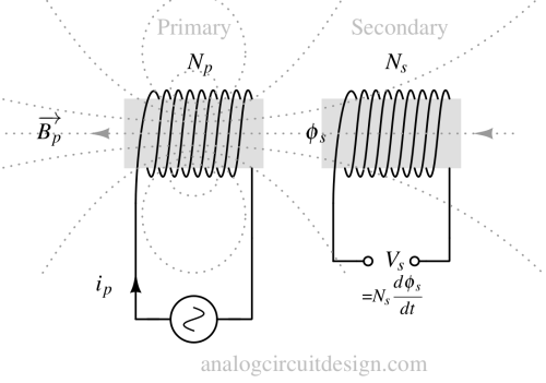
Mutual inductance occurs when you have two separate coils of wire, often referred to as the primary and secondary coils. Each coil has its own electrical circuit. When a current flows through the primary coil, it generates a magnetic field around it. This magnetic field extends into the space around the coil. If the magnetic field from the primary coil intersects with the secondary coil, a change in the current in the primary coil will cause a change in flux, that will induce a voltage in the secondary coil. This induced voltage is proportional to the rate of change of current in the primary coil.
Mathmatical representation of mutual inductance
Mathematically, mutual inductance is described by the following equation:


Vs is the induced voltage (in volts) in the secondary coil, M is the mutual inductance of the conductor or coil (H), and dip/dt is the rate of change of current in the primary coil (in amperes per second).
Mutual inductance is a property that depends on the physical arrangement of the two coils, their relative orientation, and the properties of the materials involved. It can be used to step up or down voltage levels in a transformer, where the primary and secondary coils have different numbers of turns. Transformers are important devices in electrical power distribution, allowing for efficient transmission of electricity at different voltage levels.