Solid state relay
A solid-state relay (SSR) is a semiconductor device that is an alternative to electro-mechanical relays to switch electricity to a load in many applications.
Functionality-wise, a solid-state relay is the same as electro-mechanical relays. However, with solid-state-relay, there are a few notable advantages (and disadvantages).
Advantages and Disadvantages of SSR
Following are the advantages and disadvantages of a solid-state-relay:
Advantages
SSR is superior to Electro-mechanical relays (EMRs) in many ways:
- Almost infinite switching lives.
- Immunity to EMI.
- Bounce-free operation.
- Higher operating speeds.
- Low-level control signals.
- Small package size so less board space.
- Simple circuit design. So, less component count.
- Reliable because no moving parts. So, resistant to vibration and shock.
- Unaffected by dust, gases, or other contaminants because it can be hermetically sealed.
Disadvantages
There are still some disadvantages associated with SSR :
- The output and input are not resilient against large voltage/current swings.
- The output resistance is high in comparison to EMRs.
- Expensive.
- Need to be careful with off-state leakage current.
Construction of solid state relay

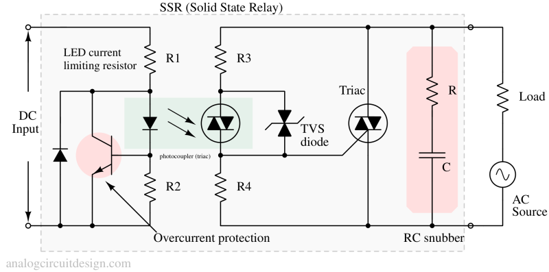
Solid state relay's input and output internal circuit may comprise of thyristors (SCRs), triacs, BJTs and MOSFETs which are designed to behave as near ideal electronic switches. To provide control signal, an optical link is normally used. This optical link is usually called optocoupler and it provides galvanic isolation. Also, there are some protection circuits like overcurrent protection, TVS diodes etc which help to enhance the longevity of the device.
RC-snubber circuit: A circuit that consists of a resistor and capacitor used to prevent faulty ignition of an SSR triac by suppressing a sudden rise in the voltage applied to the triac.
Input of solid state relay
The input of a relay is usually a low-power DC signal. One common input circuit topology is mentioned in Fig 1.
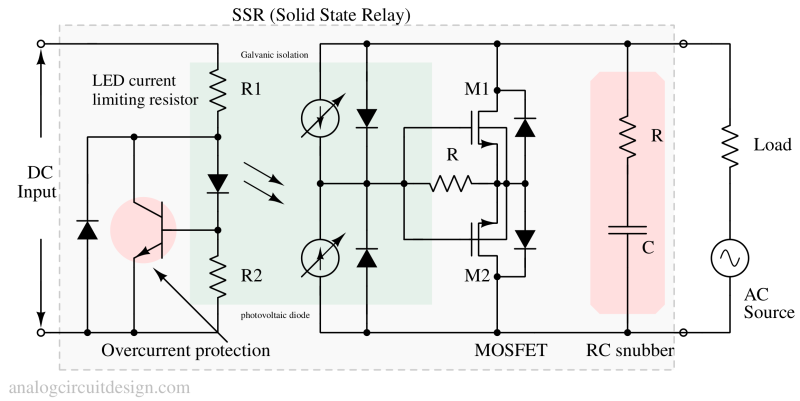
Galvanic isolation: It is essential to provide galvanic isolation between the input control signal and output signal in a relay because the output usually switches a high power (=Voltage X Current) load. In contrast, input is a low-voltage/low-power signal. Any galvanic coupling can destroy the input control circuit.
Output of solid state relay
MOSFET based outputs (AC or DC load)
High voltage capable MOSFETs are used at the output circuit to drive the loads. These are inside the SSR only. They offer very low on resistance and can turn-on/off very quickly. The way they are connected in mentioned in this diagram. The gate of both the MOSFETs are connected together such that both can be turned on simultaneously.

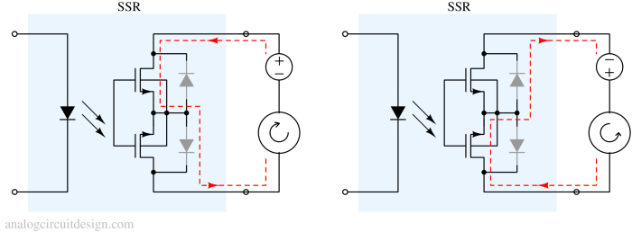
Why can MOSFET relays be used for both AC and DC loads?
It is because 2 MOSFETs are connected in series. In positive polarity first MOSFET's channel turns-on and second MOSFET's body diode turns on. In negative polarity, second MOSFET's channel turns ON and first MOSFET's body diode turns on. So, in both cases output can be turned on.

Inverse-parallel-SCR/Triacs based outputs (AC load)
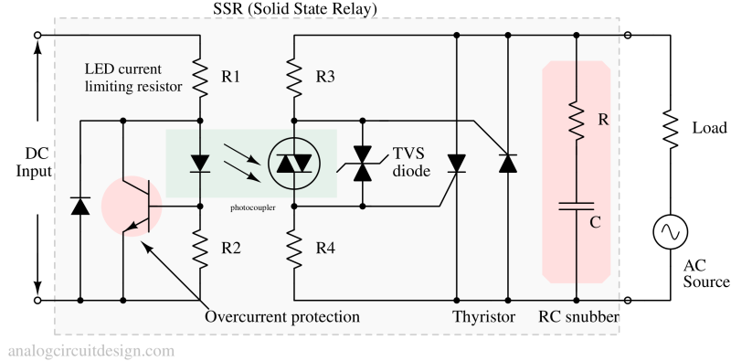
For resistive loads, there is no difference in performance between inverse-parallel-SCR and Triacs. For inductive loads like motors, inverse-parallel-SCR proves to be better because it can support higher "dV/dt".

A triac-based SSR is shown in the Fig 1.
Typical specifications of a solid state relay.
Some typical specifications of a common SSR. However, this can vary with different SSRs:
- Rated load current: 10A. (For some SSR this can be 40A also.)
- Input operating voltage : 3-32 VDC
- Input ON/OFF voltage : OFF < 1V, ON > 2.4V.
- Coupling capacitor: 8pF typical, can vary across SSRs.
- Operating frequency
- DV/DT: Important for inductive loads.
- Off-state leakage current : 6mA (max)
- Isolation voltage: 4000V
- Operating temperature : -20C to 85C.
SSR with zero crossing output control
This function makes sure that the output switch is closed only when the output voltage is near 0.
If the output switch is closed when the voltage is high, then a sudden current (inrush current) step will generate line and radiation noise. So, it is always better to let the current rise slowly from 0 rather than a large step change.
Application of solid state relays
Solid state relays are used in :
- HVAC systems : Compressor’s soft-start, fan, blower, heater and valve control.
- Lighting applications for dimming (because SSRs are able to operate silently).
- Motion control applications such as lifts, hoists conveyor systems, industrial robotics and elevators (because SSRs are immune to vibration and shock).