Verilog Data Flow Modeling
Dataflow modeling in Verilog represents circuits using Boolean equations and continuous assignments rather than explicitly listing logic gates. It lies between gate-level and behavioral modeling in abstraction and provides a more concise yet synthesizable way to describe hardware.
Key takeaways
- Uses
assignfor continuous evaluation. - Compact and synthesizable for combinational designs.
- Ideal for arithmetic, comparison, and multiplexing logic.
- Helps quickly translate logic equations into Verilog code.
Dataflow Modeling
In dataflow modeling, designers describe how data moves between inputs and outputs using logical, arithmetic, relational, and conditional operators. The most commonly used construct is the assign statement, which defines continuous assignments.
Unlike behavioral modeling (which uses procedural blocks like always and initial), dataflow modeling continuously drives values based on input changes.
Example: Simple AND Gate
module and_df (input a, b, output y);
  assign y = a & b; // Continuous assignment
endmodule
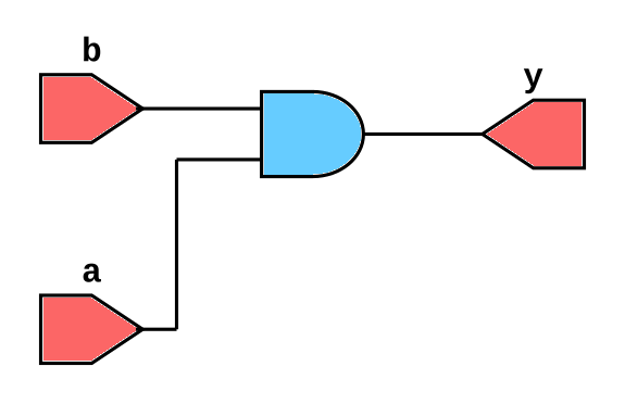
Here, whenever a or b changes, y updates automatically.
Continuous Assignment using assign
The continuous assignment statement is the foundation of dataflow modeling. It is written using the assign keyword.
Syntax
assign <net> = <expression>;
- The left-hand side must be a net type (usually
wire) - The right-hand side is an expression using operators
Example
assign y = (a & b) | (~c);
y as (a AND b) OR (NOT c). Concatenation
Concatenation in Verilog is a powerful feature that allows you to group or rearrange bits, construct buses, or split wide signals into smaller parts, using curly braces {}. It is often used in assign statements.
A basic example:
//some code
output [7:0]out;
input [3:0] a,b;

//assign statement
assign out = {a, b};
If a and b are 4-bit vectors, out becomes an 8-bit signal with a occupying the upper 4 bits and b the lower 4 bits.
Concatenation is especially useful when combining carry and sum results:
assign {carry, sum} = a + b;
Here, both carry and sum are assigned simultaneously from an arithmetic operation — carry gets the MSB of the result, and sum gets the lower bits.
You can also mix constants and signals:
assign result = {4'b0000, data_in}; // Zero-extend
Or duplicate patterns using replication:
assign pattern = {4{bit_in}}; // Repeats bit_in four times
Concatenation works with part-selects as well:
assign byte_out = {nibble_high[3:0], nibble_low[3:0]};
It’s important to note that concatenation operates only on bit vectors, not integers, and widths must match the target signal. In synthesis, concatenation is purely structural—it corresponds to wiring bits together without introducing extra hardware. In short, concatenation in assign statements gives designers flexible, compact control over signal grouping and bus manipulation.
Common Operators in Dataflow Modeling
Verilog supports a wide range of operators in dataflow descriptions. For example Arithmetic, Relational, Logical, Bitwise, Shift and Conditional operators.
More about operators in this page - Verilog Operators and Expressions
Examples
2-to-1 Multiplexer
module mux2to1_df (input a, b, sel, output y);
  assign y = sel ? b : a;
endmodule
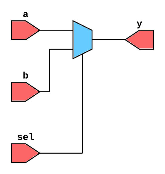
- When
sel=1, outputy=b - When
sel=0, outputy=a
This single line replaces multiple gates used in gate-level modeling.
Half Adder
module half_adder_df (input a, b, output sum, carry);
  assign sum = a ^ b;   // XOR operation
  assign carry = a & b; // AND operation
endmodule
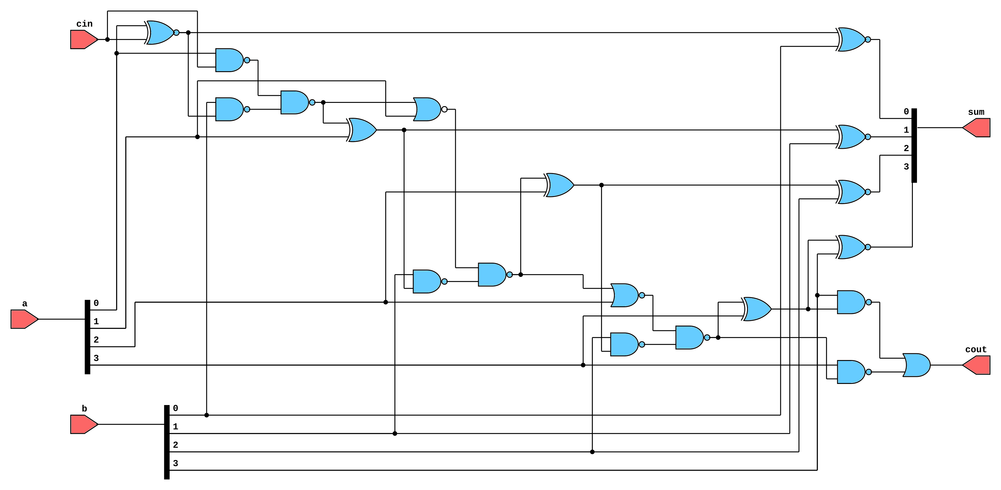
Full Adder
module full_adder_1bit (
    input A,      // 4-bit input A
    input B,      // 4-bit input B
    input cin,         // Carry In
    output sum,   // 4-bit Sum Output
    output cout        // Carry Out
);
    assign {cout, sum} = A + B + cin;
endmodule
Combines three input bits (a, b, cin) to produce sum and carry cout using Boolean logic.
4-bit Ripple Carry Adder
module ripple_adder_4bit_df (input [3:0] a, b, input cin, output [3:0] sum, output cout);
  wire [3:0] c;

  assign {c[0], sum[0]} = a[0] + b[0] + cin;
  assign {c[1], sum[1]} = a[1] + b[1] + c[0];
  assign {c[2], sum[2]} = a[2] + b[2] + c[1];
  assign {cout, sum[3]} = a[3] + b[3] + c[2];
endmodule
Explanation:
- Each bit’s sum and carry are computed through continuous assignments.
- The design flows naturally as data passes from LSB to MSB.
Comparator
module comparator_df (input [3:0] a, b, output equal, greater, smaller);
  assign equal = (a == b);
  assign greater = (a > b);
  assign smaller = (a < b);
endmodule
Explanation: Demonstrates relational operators in dataflow modeling.
Parity Generator
module parity_gen_df (input [3:0] data, output parity);
  assign parity = ^data; // XOR reduction
endmodule
Note: The reduction XOR operator (^) produces the parity bit by XORing all input bits.
Using Delays in Dataflow Modeling
Just like gate-level modeling, you can add propagation delays to continuous assignments.
Syntax
assign #delay output = expression;
Example
assign #5 y = a & b;
Explanation: The value of y changes 5 time units after a change in a or b.
Delays are mainly used in simulation, not in synthesis.
Conditional Expressions and Priority Logic
Conditional (ternary) operators make dataflow modeling highly expressive.
Example: 4-to-1 Multiplexer
module mux4to1_df (input [3:0] d, input [1:0] sel, output y);
  assign y = (sel == 2'b00) ? d[0] :
             (sel == 2'b01) ? d[1] :
             (sel == 2'b10) ? d[2] : d[3];
endmodule
Hierarchical Design Using Dataflow
Dataflow models can be instantiated just like gate-level modules to build hierarchical systems.
Example: 4-bit ALU (Arithmetic Logic Unit)
module alu4_df (input [3:0] a, b, input [1:0] sel, output reg [3:0] y);
  assign y = (sel == 2'b00) ? (a + b) :
             (sel == 2'b01) ? (a - b) :
             (sel == 2'b10) ? (a & b) : (a | b);
endmodule
Explanation: Uses ternary operators to describe multiple arithmetic/logical functions in one statement.
Advantages of Dataflow Modeling
- Compact representation — Complex logic can be written in one line.
- Closer to Boolean algebra — Directly expresses logical relationships.
- Easier debugging and readability than gate-level models.
- Fully synthesizable — Converts easily to hardware.
- Supports timing control using delays for simulation.
Limitations of Dataflow Modeling
- Limited control structures — Cannot use loops or procedural timing (
@,#inside always). - Hard to describe sequential behavior — Not suitable for registers or memory.
- Difficult for complex control logic — Behavioral modeling is preferred.
- No variable storage — Only nets (wires) can be assigned.
Best Practices for Dataflow Modeling
- Always use
assignfor continuous assignments. - Use meaningful signal names to enhance readability.
- Keep expressions short and simple.
- Use parentheses to make operator precedence explicit.
- Avoid unintentional latch inference by keeping logic combinational.
- Add
#delaysonly for simulation, not synthesis.
Example Testbench for Dataflow Model
module tb_half_adder_df;
  reg a, b;
  wire sum, carry;

  half_adder_df uut (.a(a), .b(b), .sum(sum), .carry(carry));

  initial begin
    $monitor("Time=%0t a=%b b=%b sum=%b carry=%b", $time, a, b, sum, carry);
    a=0; b=0; #10;
    a=1; b=0; #10;
    a=0; b=1; #10;
    a=1; b=1; #10;
    $finish;
  end
endmodule
Summary
Dataflow modeling is a powerful and concise Verilog technique that expresses circuit behavior using Boolean and arithmetic expressions. It is the most natural way to describe combinational logic and serves as a bridge between structural and behavioral abstraction levels.