Active bridge rectifier
Discrete diodes are commonly used in power system designs to protect against reverse current and reverse polarity events. While using a discrete diode is a straightforward solution, it has drawbacks, including high forward voltage drop, which results in increased power dissipation which shortens battery life and reduces system efficiency.

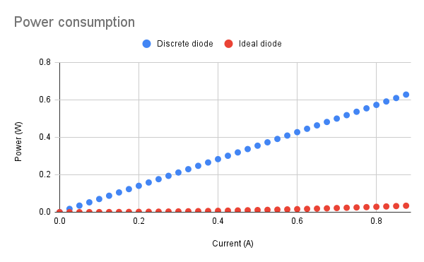
A discrete diode's power consumption is higher because of the diode voltage drop (modelled by Vd0 ~ 0.7 V and Rd = 20mΩ). If this entire discrete diode is shorted using a low resistance FET (Rds,on = 45mΩ) during forward bias as shown in Fig 1, the voltage drop can be reduced. In reverse bias, the FET will be turned-off. This addition of a FET transistor in parallel with a discrete diode is usually called Ideal or Active diode. Since the voltage drop is near zero, it is called Ideal diode. Also, the FET is actively controlled so it is called Active diode. In Fig 2, the severity of the problem is mentioned where the discrete diode dissipates lot of power in comparison to an ideal diode.
In Figure 3, we can see that the thermal signature of discrete diode is very prominent. The temperature can rise to 103°C. The \right-hand side of the figure, the thermal signature of the ideal diode is captured. The temperature does not rise beyond 27.2°C. So, this presents solid evidence of ideal diode's benefit in power supply design.

What is active bridge rectifier?
An active bridge rectifier is an electronic circuit that converts alternating current (AC) into direct current (DC) by rectifying and filtering the input waveform using ideal or active diodes.

Operation of active bridge rectifier
The active bridge rectifier comprises four power electronic switches arranged in a configuration similar to a bridge rectifier. These switches are controlled in a synchronized manner to create a path for current flow in one direction during the positive half-cycle of the input AC voltage and in the opposite direction during the negative half-cycle.
The switching operation of the active bridge rectifier is controlled by a control circuit that generates appropriate gate drive signals using zero crossing detection for the power switches. The control circuit ensures that the switches operate complementary, allowing current flow through the load in the desired direction.
Advantages of active bridge rectifiers
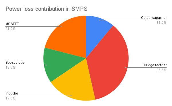
The bridge rectifier (passive) stands out as the primary source of power dissipation in power devices (as shown in pie-chart in Fig 5). To enhance efficiency, the most effective approach is to minimize the power dissipation in the bridge rectifier.
The active bridge rectifier overcomes some limitations of the traditional passive diode bridge rectifier, such as higher voltage drops and power losses.
Applications of active bridge rectifiers
Active bridge rectifiers are commonly used in applications where precise control over the rectification process is required, such as in motor drives, power supplies, and renewable energy systems. They offer advantages such as adjustable output voltage, improved power factor correction, reduced harmonic distortion, and enhanced overall system's power efficiency.