Bandpass filters
A bandpass filter allows signals between two specific frequencies to pass but attenuates signals outside these frequencies. It can be made by connecting high-pass and low-pass filters in a cascade. They create a composite filter that selectively permits signals within a defined frequency range or band (called passband) while attenuating signals outside this band (called stopband). The purpose of a low-pass filter is to separate signals with frequencies exceeding the cutoff frequency, while a high-pass filter separates signals with frequencies lower than the cutoff frequency.
Bandpass filter transfer function
The general mathematical transfer function of a bandpass filter is :
$$\cfrac{v_o(s)}{v_i(s)}=\cfrac{\cfrac{s}{\omega{}_oQ}}{1+\cfrac{s}{\omega{}_oQ}+\cfrac{s^2}{\omega{}_o^2}}$$
Frequency response of bandpass filter
To decide which bandpass filter is suitable for our application, it is important to see the frequency response of the bandpass filter. The frequency response plot shows the gain of the bandpass filter with frequency. It also shows the phase vs. frequency behavior.
Wideband bandpass filter
A wideband bandpass filter is designed to allow a wide range of frequencies within a specified passband while attenuating frequencies outside this range.
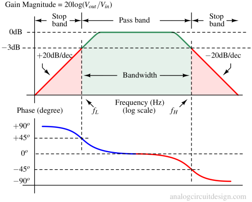
Passband: This is the range of frequencies where the filter allows the input signal to pass through with minimal attenuation. The passband is typically defined by its center frequency (fo) and bandwidth (fBW), which is the range of frequencies around the center frequency where the signal is not significantly attenuated. As shown in the above figure, the passband is the region between a lower cutoff frequency (fL) and a higher cutoff frequency (fH).
Bandwidth (fBW): The filter's bandwidth is the range of frequencies over which the filter provides significant attenuation. Basically, bandwidth is used to quantify the passband. It is typically defined as the difference between the upper cutoff frequency (fH) and lower cutoff frequency (fL). fBW = fH - fL.
Center Frequency: This is the midpoint of the passband, where the filter provides maximum gain. It is the frequency around which the passband is centered.
Stopbands: These are frequency ranges outside the passband where the filter attenuates or blocks the input signal. In a bandpass filter, there are two stopbands: one below the lower cutoff frequency (fL) and one above the upper cutoff frequency (fH). These frequencies define the boundaries of the passband.
Gain: The filter's gain is the ratio of the output signal amplitude to the input signal amplitude. In the passband, the gain is typically high, allowing the signal to pass through relatively unchanged. In the stopbands, the gain is significantly lower, indicating attenuation of the input signal.
Narrowband bandpass filter
A narrowband filter has a very narrow gain-magnitude vs frequency response, as shown in Fig 2. The pass-band is not flat as in the wideband bandpass filter. These are also called tuned bandpass filters because these are tuned to a select frequency due to very high selectivity.
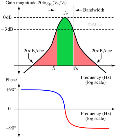
A bandpass filter is called a narrowband if the Quality factor is greater than or equal to 10. Quality factor in a bandpass filter is defined as :
$$Q=\cfrac{f_o}{f_H-F_L}=\cfrac{f_o}{f_{BW}}$$
The bandwidth of the bandpass filter is defined as fBW = fH - fL. So, the quality factor for a bandpass filter can also be defined as the ratio of center frequency (fo) and bandwidth (fBW). If we know fL and fH, fo can be calculated using the following relation:
$$f_o=\sqrt{f_L\cdot{}f_H}$$
Passive bandpass filter
Bandpass filters are never first ordered because at least two energy storage elements are present.
RC-RC bandpass filter
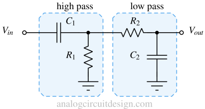
A wideband bandpass filter can be created by cascading a high-pass filter with a low-pass filter or vice-versa (shown in Fig 3). The high-pass filter's cutoff frequency is set using C1 and R1, while the low-pass filter's cutoff frequency is set using R2 and C2.
RLC bandpass filter

A bandpass filter can also be created using a resistor, inductor, and capacitor, as shown above in Fig 4. Since it is a series RLC circuit, the quality factor (Q) of the circuit is defined as :
$$Q=\cfrac{1}{R}\sqrt{\cfrac{L}{C}}$$
A high-quality factor is achievable by simply reducing the resistor value. So, a narrowband filter can be made with center frequency at :
$$f_{center}=\cfrac{1}{\sqrt{LC}}$$
Active bandpass filter
Active bandpass filters utilize active components, typically operational amplifiers (op-amps) and transistors, to achieve gain in the pass-band region. Active bandpass filters also help achieve high-quality factors without using inductors (e.g., Tow-thomas Biquad filter).
Wideband bandpass filters
The filters in the wideband category have a maximum attainable quality factor of 1/2. That happens when the high pass-time constant equals the low pass-time constant.
Simple RC-RC bandpass filter
A high-pass filter can be followed with a gain stage (non-inverting opamp configuration) and a low-pass filter. The bandpass filter setup is shown in Fig 5. The high pass filter is made using R1 and C1. The low pass filter is made using R2 and C2. The gain is provided by opamp and resistors Rf and Rg. The passband gain is given by :
$$G=1+\cfrac{R_f}{R_g}$$
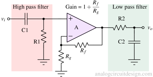
The transfer function of a simple RC bandpass filter is mentioned below:
$$\cfrac{v_o}{v_i}=\left(1+\cfrac{R_f}{R_g}\right)\cfrac{sC_1R_1}{(1+sR_1C_1)(1+sR_2C_2)}$$
Comparing the above equation with the general equation of the bandpass filter, we obtain the:
$$\omega{}_o=\cfrac{1}{\sqrt{R_1C_1R_2C_2}}$$
and,
$$Q=\cfrac{\sqrt{R_1C_1R_2C_2}}{R_1C_1+R_2C_2}$$
The maximum value of Q could be 1/2. Therefore, it does not have high selectivity to pass only a single frequency and attenuate others. So, it is categorized as a wideband bandpass filter.
Inverting gain bandpass filter
A high-pass filter can be made using an amplifier in the inverting gain configuration. The feedback network makes the low pass filter using Rf and Cf (sets the fH). The input network makes the high pass filter using Ri and Ci (sets the fL). Rf and Ri set the pass band gain.
$$G=-\cfrac{R_f}{R_g}$$
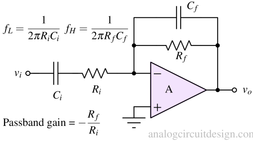
The transfer function of an inverting amplifier-based bandpass filter is mentioned below:
$$\cfrac{v_o}{v_i}=\left(-\cfrac{R_f}{R_g}\right)\cfrac{sC_iR_i}{(1+sR_iC_i)(1+sR_fC_f)}$$
Comparing the above equation with the general equation of the bandpass filter, we obtain the:
$$\omega{}_o=\cfrac{1}{\sqrt{R_iC_iR_fC_f}}$$
and,
$$Q=\cfrac{\sqrt{R_iC_iR_fC_f}}{R_fC_f+R_iC_i}$$
Here, the Q cannot exceed 1/2, also categorized as a wideband bandpass filter.
Narrowband bandpass filter
The following filters can achieve higher quality factors because of inductors or multiple feedback paths. Higher Q increases the selectivity and narrows the passband.
Active RLC bandpass filter
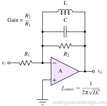
A parallel LC bandpass filter typically consists of a capacitor in parallel with an inductor at the feedback network of an opamp. This configuration provides zero gain at low and high frequencies, allowing signals within the specified passband to pass through relatively unattenuated. At frequency fcenter, the LC tanks appear as open circuits. That makes the gain at fcenter to be :
$$G=-\cfrac{R_2}{R_1}$$
Rauch bandpass filter
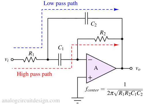
Tow-thomas bandpass filter (Biquad)
Sometimes, using a sizeable physical inductor to make a low center frequency bandpass filter is not feasible. For example, audio integrated circuits where the frequency range is < 20kHz. Either the capacitor or the inductor has to become large. So, in the active RLC bandpass filter, the physical inductor is replaced with a circuit that acts as an inductor. This circuit is called a gyrator.
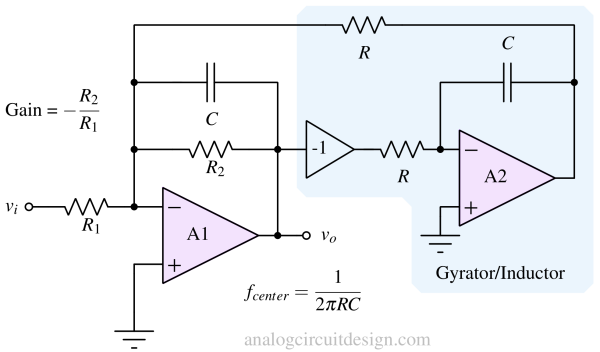
The gyrator is made using opamp, resistors, and capacitors. The impedance. It takes the output of the opamp A1 and injects a current at that inverting terminal of A1 that mimics an inductor's current. The current injected into the inverting node of A1 equals :
$$i=\cfrac{v_o}{sR^2C}$$
the above expression seems similar to an inductor current:
$$i=\cfrac{v_o}{sL}$$
Therefore,
$$L=R^2C$$
So, the center frequency is :
$$f_o=\cfrac{1}{2\pi{}\sqrt{LC}}=\cfrac{1}{2\pi{}\sqrt{R^2C\cdot{}C}}=\cfrac{1}{2\pi{}RC}$$
and Quality factor Q is (assuming R2 = R1 = RQ):
$$Q=\cfrac{R_Q}{R}$$
Transient response of bandpass filters
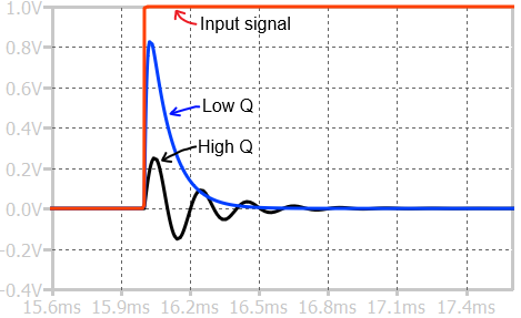
The step response of a bandpass filter is shown above. Both bandpass filters are tuned to the same frequency (~15kHz). The low Q bandpass response is similar to exponential decay. The high Q bandpass response is like an exponential and sinusoid decay.
Applications of bandpass filters
Communication Systems: It is needed in channel selection and frequency discrimination, facilitating signal isolation amidst noise and interference in communication systems like radio receivers.
Audio Processing: These filters enable equalization, tone shaping, and effects processing, allowing manipulation of specific frequency bands to enhance sound characteristics.
Medical Devices: In ECG and EEG machines, BPFs are used to isolate and amplify specific frequency components of physiological signals, extracting vital information while mitigating noise.
Radar and Sonar Systems: They are integral to radar and sonar systems, aiding in target detection, range determination, and noise reduction by filtering out unwanted frequencies and interference.
Wireless Communication: In wireless communication systems like cellular networks and Wi-Fi, bandpass filters are crucial in transmitter and receiver circuits, ensuring efficient spectrum utilization and reliable communication by filtering out interference and adjacent channel signals.