Bridge rectifier
A bridge rectifier is an electrical circuit that converts alternating current (AC) into direct current (DC). It is classified as a full wave rectifier circuit because the output of the circuit is always positive even if the input of the circuit is negative. Unlike half-wave rectifiers, which discard the negative amplitude, the bridge rectifier preserves both polarities, classifying it as a full-wave rectifier. A key advantage of a bridge rectifier is that it eliminates the need for an expensive center-tapped transformer, thereby reducing both the size and cost of the circuit.
Construction of bridge rectifier
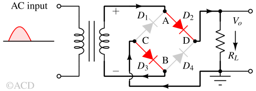
The diagram below illustrates the construction of a bridge rectifier. This circuit consists of four diodes (D1, D2, D3, and D4) and a load resistor (RL) arranged in a closed-loop configuration to efficiently convert alternating current (AC) into direct current (DC).

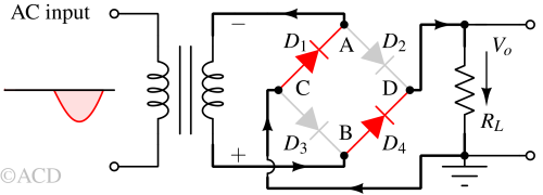
The input signal is applied to terminals A and B. In contrast, the output DC signal is obtained across the load resistor RL, which is connected between terminals C and D. The four diodes are configured so that only two diodes conduct electricity during each half cycle. Diodes D2 and D3 conduct the electric current during the positive half cycle. Conversely, diodes D1 and D4 conduct the current during the negative half cycle.
Working principle of bridge rectifier
To understand the operation of a bridge rectifier, the input signal's positive and negative half cycles can be analyzed separately.
During positive half-cycle of input signal

During the positive half cycle, terminal A becomes positive while terminal B becomes negative. This causes diodes between D2 and D3 to become forward-biased and conduct, while D1 and D4 become reverse-biased and do not conduct.
During negative half-cycle of input signal

During the negative half-cycle, terminal A becomes negative, and terminal B becomes positive. This causes diodes D4 and D1 to become forward-biased and conduct, while diodes D2 and D3 become reverse-biased and do not conduct.
In both the positive and negative half cycles, the direction of the current through RL is the same. This means that the voltage at the output is always positive.
Ripple reduction and smoothing capacitors
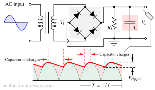
The output of the rectifier is not pure DC but rather a pulsating DC, known as a ripple voltage. This ripple can be reduced by using smoothing capacitors in parallel with the load resistor (RL), which converts the ripple voltage into a smoother DC voltage. Aluminium electrolytic capacitors are commonly used because they are inexpensive, compact, and readily available.

When the pair of diodes turn on, it charges the capacitor in parallel with supplying current to the load. When the diode turns off, the charged capacitor provides the load current. In this process, the capacitor starts discharging.
$$V_{ripple}simeq{}\text{Slope}times{}\text{Time interval}=\cfrac{V_o}{R_LC}\cfrac{1}{2f}$$
Note that the Vripple of the full wave rectifier is half of that of the half wave rectifier.
Characteristics of bridge rectifier circuit
The Bridge Rectifier has three main characteristics, as listed below:
- Ripple Factor
- Peak Inverse Voltage (PIV)
- Efficiency
Ripple factor
The ripple factor indicates the stability of the DC power after it has been converted from AC. In a bridge rectifier, the ripple factor is typically relatively low, meaning the DC power is reasonably stable with minimal fluctuations. This stability is crucial for applications requiring a consistent power supply, such as phones and computers. The mathematical formula for the ripple factor (RF) is as follows:
$$RF=\cfrac{1}{\sqrt{3}}\cfrac{V_{rms}}{V_{dc}}$$
Peak Inverse Voltage (PIV)
Peak Inverse Voltage (PIV) represents the maximum voltage the diodes in a bridge rectifier can withstand without failing. It is usually the avalanche limit of each diode. Each diode in the bridge rectifier must be capable of handling the full AC voltage, so the peak inverse voltage should be higher than the maximum AC voltage (inclusive of voltage fluctuations).
Efficiency
Efficiency measures the effectiveness of a bridge rectifier in converting AC power to DC power. It indicates how much input energy is successfully converted into usable DC power. Bridge rectifiers are typically quite efficient, meaning most input power is transformed into useful DC power with minimal waste.
The primary source of power loss in bridge rectifiers is due to the forward voltage drop of diodes. This drop can be reduced by using an active bridge rectifier. In an active bridge rectifier, the voltage drop is reduced by using a parallel FET switch. To know more, please visit the active bridge rectifier page.
The mathematical representation is as follows:
$$\eta{}=\cfrac{\text{DC output power}}{\text{AC input power}}times{}100$$