Capacitor specifications
Capacitors have several key specifications that define their performance and suitability for various applications. This article explores the essential specifications of capacitors, helping engineers and designers make informed choices based on their application requirements. Some of the most important capacitor specifications are mentioned below.
Polarity
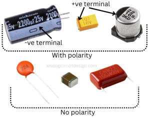
Some capacitors, like electrolytic and tantalum capacitors, are polarized and must be connected with the correct polarity. If these are not connected in the correct polarity, they may be destroyed. Non-polarized capacitors can be connected in either direction.
Capacitance (C)
Capacitance is the fundamental property of a capacitor and is measured in Farads (F). It determines the amount of electrical charge a capacitor can store per unit voltage. Higher capacitance values indicate a greater ability to store charge.
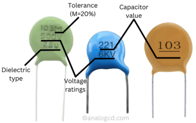
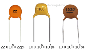
The capacitance value of ceramic capacitors is indicated by a three-digit number and an alphabet printed on the capacitor, as illustrated in the figure. The first two digits specify the capacitance in picofarads (pF), while the third digit serves as a multiplier, showing how many zeros should be appended to the first two digits. The alphabet denotes the tolerance of the capacitor.
| Alphabet | Tolerance |
|---|---|
| C | ±0.25pF |
| D | ±0.5pF |
| E | ±1pF |
| G | ±2% |
| J | ±5% |
| K | ±10% |
| L | ±15% |
| M | ±20% |
| N | ±30% |
| Z | +80%, -20% |
Voltage rating (V or WVDC)
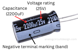
The voltage rating of a capacitor, expressed in volts (V) or WVDC (Working Voltage Direct Current), represents the maximum voltage the capacitor can safely handle without breaking down or experiencing electrical breakdown. Choosing a capacitor with an appropriate voltage rating is crucial to prevent damage.
Surge voltage
Surge voltage is a temporary spike in voltage that surpasses the rated voltage due to external influences. Capacitors are typically built to endure surge voltages ranging from 1.1 to 1.15 times their rated voltage. However, prolonged exposure to such voltage surges may lead to failure. To ensure reliability and longevity, it is essential to keep the applied voltage within the specified rating.
Tolerance
Capacitors are manufactured with a specified capacitance tolerance, which indicates how closely the actual capacitance value will match the rated value. Common tolerances include ±5%, ±10%, and ±20%. Tighter tolerances indicate greater accuracy.
Dielectric material
The dielectric material between the capacitor plates determines its performance characteristics. Different dielectric materials offer varying levels of capacitance, voltage rating, temperature stability, and other properties. Common dielectric materials include ceramic, aluminum electrolytic, tantalum, polyester (Mylar), polypropylene, and more.
Table : Ceramic Dielectric Classes
| Class | Examples (EIA Code) | Material Type | Temperature Sensitivity/Stability (TCC) | Capacitance Range | Capacitance Volumetric density | Insulation resistance | Key Applications |
|---|---|---|---|---|---|---|---|
| Class I | C0G (NP0), C0H, C0K | Non-ferroelectric ceramics, low-loss (tan δ < 0.15%), High-Q, Low-permittivity | Very stable (<30 ppm/°C) | Low (pF to nF range) | Low | >10GΩ | Frequency control, RF circuits, precision timing (e.g., radio, TV tuners) |
| Class II | X7R, X5R, Y5V, Z5U | Ferroelectric ceramics (barium titanate-based). High-permittivity, Low-Q (tan δ < 3.5%) | Moderate stability (±15% or more) | Medium to high | High | >1GΩ | General decoupling, filtering, power supply bypassing |
| Class III | Z5U, Y5V | High-permittivity ceramics (ferroelectric), Poor tangent loss angle, Not standardized | Poor stability (large variation) | Very high (µF range) | Very High | >100MΩ | Bulk capacitance, low-frequency filtering (when precision is not critical) |
Class II capacitors exhibit piezoelectric behavior, which enables them to act as both microphones and buzzers. In contrast, Class I capacitors do not have this issue.
Insulation resistance (IR)
Insulation Resistance (IR) represents the ability of a capacitor's dielectric material to prevent leakage current. It is the inherent resistance of the dielectric itself. It is determined by using ohms law; applying voltage and measuring leakage current.
Temperature coefficent of capacitors (TCC)
The temperature coefficient of a capacitor (TCC) is the maximum change in its capacitance over a specific temperature range. It's usually expressed in parts per million per degree Kelvin ppm/K for Class-I capacitors and in percentage (%) for Class-II capacitors.
$$\cfrac{\Delta{}C}{C}=10^6\times{}\alpha{}\times{}\Delta{}T$$
ΔC is capacitance change. α is temperature coefficient in ppm/K and ΔT is temperature change in Kelvin (K). The temperature coefficients of Class I and Class II capacitors can be derived using the codes provided by the manufacturer. The code tables (EIA standard) are mentioned below :
| Class I Ceramic Capacitor Codes (EIA alphanumeric code) | |||||
|---|---|---|---|---|---|
| First character | Second character | Third character | |||
| Letter | Value | Digit | Multiplier 10x | Letter | Tolerance |
| C | 0.0 | 0 | -1 | G | +/-30 |
| B | 0.3 | 1 | -10 | H | +/-60 |
| L | 0.8 | 2 | -100 | J | +/-120 |
| A | 0.9 | 3 | -1000 | K | +/-250 |
| M | 1.0 | 4 | +1 | L | +/-500 |
| P | 1.5 | 6 | +10 | M | +/-1000 |
| R | 2.2 | 7 | +100 | N | +/-2500 |
| S | 3.3 | 8 | +1000 | ||
| T | 4.7 | ||||
| V | 5.6 | ||||
| U | 7.5 |
For example, C0G code means temperature cofficient is 0.0 x 0.1 ppm/K ± 30%. This is the best available capacitor in the market in terms of temperature coefficient.
| EIA alphanumeric code | Ceramic name | Temperature coefficient α (ppm/K) | Tolerance (ppm/K) |
|---|---|---|---|
| C0G | NP0 | 0 | ±30 |
| H2G | N33 | −33 | ±30 |
| L2G | N75 | −75 | ±30 |
| M7G | P100 | 100 | ±30 |
| P2H | N150 | −150 | ±60 |
| R2H | N220 | −220 | ±60 |
| S2H | N330 | −330 | ±60 |
| T2H | N470 | −470 | ±60 |
| U2J | N750 | −750 | ±120 |
| Q3K | N1000 | −1000 | ±250 |
| P3K | N1500 | −1500 | ±250 |
EIA alphanumeric codes are different from Ceramic names. Some ceramic names are mentioned in table above.
| Class II Ceramic Capacitor Codes (EIA alphanumeric code) | |||||
|---|---|---|---|---|---|
| First character | Second character | Third character | |||
| Letter | Low Temp | Digit | High Temp | Letter | Change |
| X | -55C (-67F) | 2 | +45C (+113F) | D | +/-3.3% |
| Y | -30C (-22F) | 4 | +65 (+149F) | E | +/-4.7% |
| Z | +10C (+50F) | 5 | +85 (+185F) | F | +/-7.5% |
| 6 | +105 (+221F) | P | +/-10% | ||
| 7 | +125 (+257F) | R | +/-15% | ||
| S | +/-22% | ||||
| T | +22% / -33% | ||||
| U | +22% / -56% | ||||
| V | +22% / -82% |
Self resonance frequency (SRF)
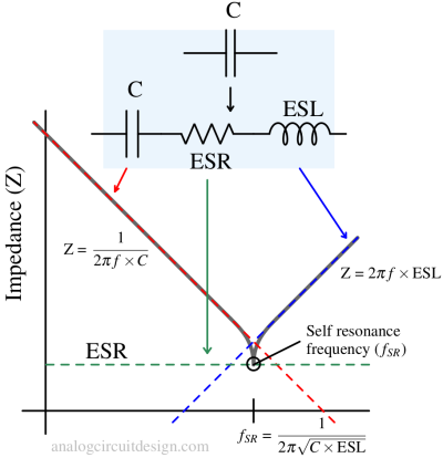
The self-resonant frequency (SRF) of a capacitor refers to the frequency at which the inductive reactance of the capacitor (mostly lead and contact inductance) and its primary capacitive reactance cancel each other out. Beyond this frequency, the capacitor behaves like an inductor, and its impedance starts growing instead of reducing.
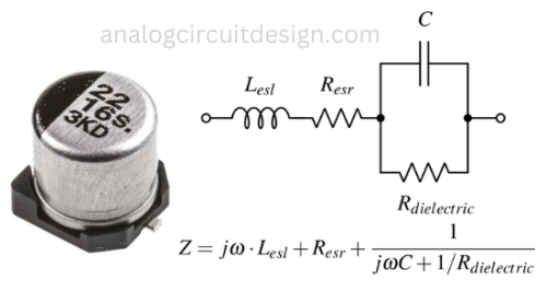
The model of the capacitor is mentioned below in Figure 5.
Equivalent series inductance (ESL)
ESL represents the inductive component of a capacitor's impedance and is significant in high-frequency applications. Lower ESL values are preferred for minimizing high-frequency degradation of capacitance. At high frequencies, a pure capacitor (without ESL) should behave as a short. However, in the presence of inductance, the impedance at high-frequency increases since it is present in series as shown in Fig 5.
Equivalent series resistor (ESR)
ESR represents the internal resistance of a capacitor and is measured in ohms (Ω). These are generated by electrode/dielectric body loss. A lower ESR value indicates better efficiency and higher performance, especially in high-frequency applications. At high frequencies, a pure capacitor (without ESR) should behave as a short. However, in the presence of resistance, the impedance at high frequency remains constant and does not decrease. Since it is present in series as shown in figure above, it introduces a pole-zero which can widen the operating bandwidth and make LDOs unstable.
Tangent of loss angle
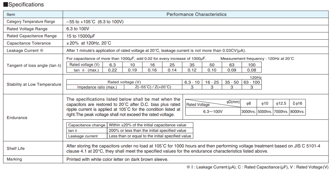
The tangent of the loss angle (often denoted as tan δ) is the ratio of the imaginary component of impedance to the real component in a circuit. It is also referred to as the "dissipation factor" and is used to characterize losses in AC circuits. The value of ESR is not mentioned directly in the datasheets, however value of tan δ allows us the measure the ESR indirectly
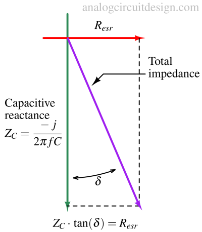
The dissipation factor (DF) is a measure of loss-rate of energy during oscillation. It is ratio of power dissipated in the ESR and power stored in the capacitor. It is equal to tan δ (The tangent of loss angle).
$$\tan{\delta{}}=\cfrac{i^2R_{esr}}{i^2Z_C}=\cfrac{R_{esr}}{Z_C}=\text{DF}$$
Leakage current
Leakage current, measured in microamperes (µA) or nanoamperes (nA), is the small amount of current that can flow through a capacitor when it's fully charged. Lower leakage currents are preferable in applications where energy efficiency is critical.
Ripple current rating
In AC or pulsating DC applications, capacitors may experience ripple currents. The ripple current rating specifies the maximum allowable AC current without causing excessive temperature rise or damage to the capacitor. Higher current may flow through the ESR can cause heating which impacts longevity and performance.
Life expectancy and endurance
Different types of capacitors have different lifespans. For example, electrolytic capacitors typically have a shorter lifespan compared to ceramic or film capacitors. Capacitors subjected to electrical stress beyond their specifications or exposed to overvoltage conditions may degrade more quickly. The environment in which the capacitor is used can affect its lifespan. Factors such as humidity, vibration, and exposure to corrosive substances can impact a capacitor's longevity.
Reliability
In the realm of applications (Aerospace, Automotive, Defense, and Medical) that exhibit a low tolerance for device failures, the capacitors are meticulously manufactured and rigorously tested in accordance with well-defined standards (MIL-HDBK-217F Notice 2). The primary objective of this stringent approach is to furnish a statistically robust guarantee of device reliability. The devices are procured through documentation. Such channels facilitate the tracking of a component's history throughout the entire production process. This traceability is essential for ensuring device integrity and streamlining the root cause analysis in the event of a malfunction.
Size and form factor
Capacitors come in various physical sizes and shapes, which can impact their suitability for specific applications. Factors like package type, footprint, and lead spacing should be considered.