Capacitors
Capacitors are two terminal passive devices which store charges resulting in a potential difference across its two terminals. It stores electrical energy in form of electrical field. The amount of charge stored by a capacitor is directly proportional to its "capacitance". So, the term "capacitance" is used to quantify a capacitor.
If voltage across the two terminals of a capacitor is "V" and the capacitance is "C" then the charge "Q" stored is :
$$Q=CV$$
Parallel plate capacitor
The most common and simple form of capacitor is parallel plate capacitor. Almost every capacitor's cross section can be analysed as a parallel plate capacitor.

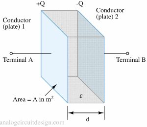
A capacitor is made up of 2 conductors (or plates) separated by an insulator (or a dielectric). If one of the plates is given a charge "+Q" then an equal an opposite charge "-Q" is induced in the another plate. This capacitor is holding "Q" charge in it. The capacitance of a parallel plate capacitor is :
$$C=\cfrac{A}{d}\epsilon{}$$
Here "A" denotes the area of each conductor, and "d" denotes the distance between the parallel plate. (epsilon) is the permittivity of the dielectric material (electrical insulator). It is a constant depending on the material. Usually to increase the capacitance some special dielectric material is used which have high permittivity.
We should note that, larger area of the parallel plates or smaller distance between the parallel plate results in larger capacitance.
If a parallel plate capacitor stores "Q" charge, then this creates an electrical field from plate having positive charge to plate having negative charge.
In practical capacitors, this electric field exerts an internal force which tries to bring the 2 plates together. If these plates are closer, the capacitance increases. That is captured by incremental capacitance :
$$C = \cfrac{dQ}{dV}$$
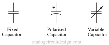
Circuit symbol

Capacitance
Capacitance is measured in farads. 1 Farad of capacitance is defined as one columb of equal and opposite charge on the 2 conductors of the capacitors causes 1 volt across the capacitor.
We often use capacitance in terms of microfarads (μF, or (10^{-6}) of a farad), or picofarads (pF, or (10^{-12}) of a farad).
Example: To make an RC low pass filter with -3dB bandwidth of 1kHz. Let's assume we have a 1kOhm resistor while the capacitance required is yet to be known.
$$f = \cfrac{1}{2\pi{}RC}$$
$$\implies{}C = \cfrac{1}{2\pi{}fR}$$
$$C=0.159\mu{}\text{F}$$
Types of capacitors
There are different types of capacitors found in the market which varies in terms of cost, size, voltage ratings etc. Some types of capacitors are Ceramic Capacitors, Aluminum Electrolytic Capacitors, Tantalum Electrolytic Capacitors, Polyester Film Capacitors, Polypropylene Film Capacitors, Mylar Capacitors, Multilayer Ceramic Capacitors (MLCCs), Ceramic Disc Capacitors, Variable Capacitors, Supercapacitors (Ultracapacitors), Mica Capacitors, Paper Capacitors etc.
To learn more about each capacitor please visit this page: Types of capacitors
Current through a capacitor
Since there is a insulator in between the parallel plate, no current can flow through a capacitor if the terminals of the capacitor is held with a constant DC voltage. However, if the voltage across the capacitor is changed with time, then the charge stored in it also changes with time. This change in stored charge results in a current. So, a current can flow only if voltage is varied with time.
$$Q=CV$$
$$\cfrac{dQ}{dt}=C\cfrac{dV}{dt}=i$$
The above equation means that if a the voltage is linearly varied across a capacitor, the current would be constant. Also, if voltage is constant, current is zero.
Applications
There are hardly any practical circuits where capacitors are not used. Following are some of the applications of capacitors :
- AC coupling, DC blocking, Bypassing
- Supply decoupling
- Analog filters
- Frequency response of audio circuits
- Energy storage elements in switching DC-DC converters.
- Stability of analog circuits
- Analog to digital conversion circuits
- Capacitive sensing (e.g., touchscreen)
- Snubber capacitor (in presence of inductors)