Capacitors in AC circuits
In AC circuits, the voltage and current waveform are sinusoidal. The capacitor act as a impedance where the current and voltage are out of phase. The current leads the voltage by 90°.
How capacitor behaves in AC circuits?

How current flows through a seemingly open circuit?
We know that when a capacitor is charged from zero to voltage V1, it would require the source to supply C.V1 amount of charge. If the voltage is changed to V2 in time ΔT, the source should supply the C.(V1-V2) charge. This extra charge over time ΔT is the current (I).
This explains intuitively, why a current can flow through a seemingly open circuit when a variable voltage is applied.
How to intuitively understand capacitor impedance?
As mentioned in the previous section, the current (I) is inversely proportional to ΔT. If ΔT is small, the current supplied to charge/discharge the capacitor is high. That explains why conductance is higher with frequency. In other words, the reactance (XC) is lower at higher frequencies.
With higher capacitance, the capacitor can carry more charge, hence more current can flow. So, higher capacitance means lower reactance (XC).
So, capacitor reactance (XC) is inversely proportional to frequency and capacitance :
$$X_C=\cfrac{1}{2\pi{}\cdot{}f\cdot{}C}$$
Understanding the phasor diagram of a capacitor
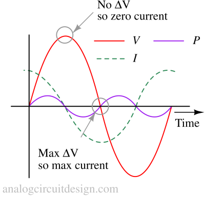
If we plot the voltage and current through a capacitor, the instantaneous current is zero whenever the instantaneous voltage is at a peak where there is zero change. The instantaneous current is at a peak wherever the voltage change is maximum (near zero crossing).
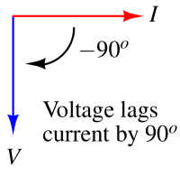
The voltage wave is -90° out of phase with the current wave. Looking at the graph (shown above), the current wave seems to have a “head start” on the voltage wave; the current “leads” the voltage, and the voltage “lags” behind the current.
In AC analysis, the impedance offered by a capacitor having value C at frequency ω is denoted by :
$$Z_{C}=-\cfrac{j}{\omega{}C}$$
Capacitor in low pass filter
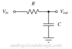
The above figure shows a simple low pass filter using R and C. The capacitor acts as an open circuit at a lower frequency. So, there is no voltage current through the capacitor and hence no voltage drop across the resistor. This means that Vout is similar to Vin.
At higher frequencies (ω > 1/RC), the capacitor starts drawing a significant current. This current drops voltage across the resistor and Vout falls with frequency. At very high frequencies, the capacitor acts as a short and Vout nears 0.
Actual capacitor at high frequency
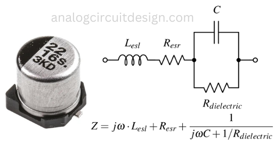
Effective series inductance (ESL or Lesl) and resistance (ESR or Resr) describe the parasitic inductances and resistances that limit the capacitor behavior at high frequencies.
ESL is mainly caused by the capacitor's internal lead lengths, package design, and the geometry of its construction. The longer and thinner the leads and connections, the higher the ESL. In high-frequency applications or fast-switching circuits, the ESL can cause overshoots impede the current, and limit capacitor performance. The capacitor is supposed to take more current at high frequency however ESL will limit that.
ESR is typically caused by the internal resistance of the capacitor's electrodes and the dielectric material itself. It can also be affected by temperature and frequency. In practice, ESR can lead to energy losses in a capacitor.
Capacitor in high pass filter
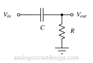
In a passive high pass filter using R and C (shown above), at low frequencies, the capacitor acts as open. So, there is no current through it and resistor R. So, no voltage drop is created across R. Therefore Vout is 0.
With higher frequency (ω > 1/RC), the capacitor is allowing current to flow. This elevates the Vout because a current is flowing through resistor R. Eventually, at a very high frequency, the capacitor acts as short and Vout=Vin.
Reactance of a 1uF capacitor across frequency
| Frequency (Hz) | Reactance (Ohms) |
|---|---|
| 50 | 3184 |
| 60 | 2653 |
| 100 | 1592 |
| 1000 | 159 |
| 10k | 15.9 |
| 100k | 1.59 |
| 1M | 0.159 |
Power factor correction
Power factor correction is a technique that improves the power factor of an AC circuit by reducing the reactive power that is present in the circuit. Reactive power is the power that does not do any useful work but is needed to maintain the voltage and current in the circuit. Reactive power is caused by inductive loads, such as coils, transformers, motors, etc., that create a phase difference between the voltage and the current. Power factor correction uses capacitors in parallel with the load to cancel out the effect of the inductive loads and make the voltage and current more in phase. This reduces the apparent power, which is the product of voltage and current, and increases the true power, which is the power that actually does work.