Clipper circuits
Clipper circuits, also known as clippers, limiters, or slicers, selectively remove a portion of an input signal without affecting (distorting) the remaining waveform. They serve as wave-shaping circuits controlling the shape of the output waveform using linear and non-linear elements without using energy-storing components. In diode clipping circuits, the diode, in a forward-biased state, permits current flow, while in reverse bias, no current flows, maintaining unaffected voltage.
These circuits act as protection devices for voltage-sensitive electronic equipment, preventing damage from high-amplitude voltages. Typically, clipper circuits incorporate resistor-diode combinations in their circuitry.
Types of clipper circuits
Series clipper circuit
- Positive Series Clipper: Allows only the positive half-cycle of the input signal.
- Negative Series Clipper: Allows only the negative half-cycle of the input signal.
Parallel or shunt clipper circuit
- Shunt positive Clipper: Clips the positive portion of the signal by diverting the current to the ground. The diode comes in parallel with the load resistor. The diode's anode is connected to the output node, and its cathode is connected to the ground.
- Shunt negative Clipper: Clips the negative portion of the signal by directing the current to the ground. The diode comes in parallel with the load resistor. The diode's anode is connected to the ground, and its cathode is connected to the output node.
Biased clippers
- Positive Biased Clipper: Adds a bias voltage to the diode, shifting the diode's trigger voltage above 0V by the voltage set by the voltage source.
- Negative Biased Clipper: Adds a negative bias voltage, shifting the diode's trigger voltage below 0V by the voltage set by the voltage source.
Series clipper circuit
The diode comes in series with the output load in a series clipper circuit, as shown in this section. The diode polarity can be changed to obtain positive or negative clipping.
Series positive clipper circuit without bias

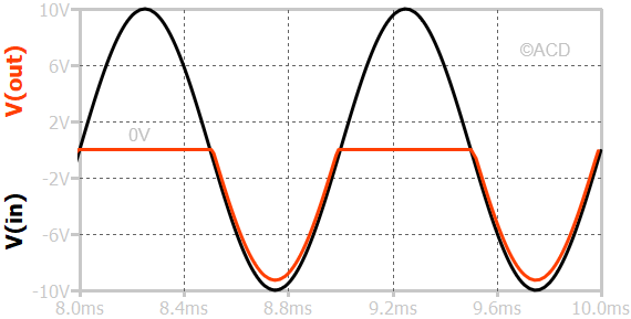
During the positive half of the input waveform, the diode undergoes reverse biasing, functioning as an open switch. This leads to zero current through the diode and load resistor, making output voltage zero during positive input voltage.
Conversely, during the negative half of the input waveform, the diode is forward-biased, acting as a closed switch. This allows current to flow from the diode. If the drop across the diode is considered negligible, the voltage across the load resistor equals the input voltage.
Series negative clipper circuit without bias

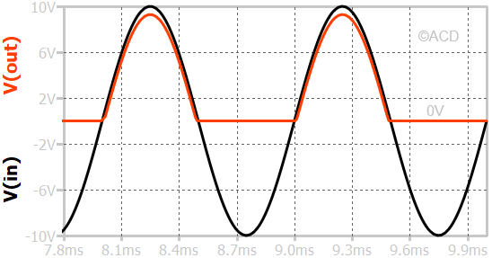
During the positive half cycle, the diode is forward-biased as a closed switch (or a short). This leads to the required current flowing through the diode and load resistor, making the output voltage equal to the input voltage (diode drop considered zero).
During the negative half of the input waveform, the diode is reversed-biased, acting as an open switch. This does not allow current to flow from the diode and the load resistor. If no current flows through the load resistor, the output voltage becomes zero, as shown in Fig 4.
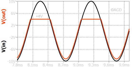
Series positive clipper circuit with bias

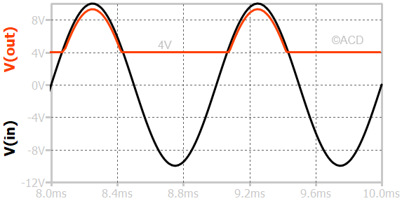
The diode becomes forward biased when the anode voltage is greater than bias voltage (V2\=4V). So, the output voltage equals input voltage only above 4V as shown in Figure. Below 4V, the diode becomes reversed biased and act as a open circuit. Now no current flows through the the load resistor. Therefore, the output voltage is 4V + 0 X 1kΩ = 4V.
During the negative cycle of the input voltage, the input voltage is still less than 4V so there no current in the load and output voltage is still 0V.

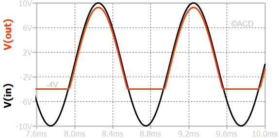
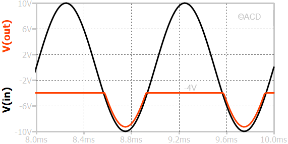
The diode becomes forward-biased when the anode voltage exceeds the cathode voltage set by V2, which equals -4V. So, the output voltage equals the input voltage only above -4V. Below -4V, the diode becomes reversed-biased and acts as an open circuit. Now, no current flows through the the load resistor. Therefore, the output voltage is -4V + 0A X 1kΩ = -4V.
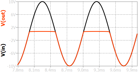
Series negative clipper circuit with bias

The diode becomes forward-biased only when the cathode voltage (input node) is below the voltage set by V2 at the anode (output node), which is +4V. So, the output voltage equals the input voltage only below +4V. Above +4V, the diode becomes reversed-biased and acts as an open circuit. Now, no current flows through the the load resistor. Therefore, the output voltage is +4V + 0A X 1kΩ = +4V.

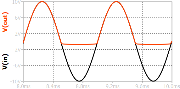
The diode becomes forward-biased only when the cathode voltage (input node) is below the voltage set by V2 at the anode (output node), which is -4V. So, the output voltage equals the input voltage only below -4V. Above -4V, the diode becomes reversed-biased and acts as an open circuit. Now, no current flows through the the load resistor. Therefore, the output voltage is -4V + 0A X 1kΩ = -4V.
Shunt clipper circuit
In the shunt clipper circuits, the diode is connected in parallel with the output load, as shown in the following section. The diode polarity can be changed to obtain negative or positive clipping functionality.
Shunt positive clipper circuit without bias

In the above figure, a shunt-positive clipper circuit is mentioned. The diode is connected in parallel (also called a shunt) with the load (not shown), called a shunt-clipper circuit. Please note that the anode of the diode is connected to the output voltage, while the cathode of the diode is connected to the ground. This means that the output voltage has to be greater than 0V for the diode to be turned on.
When a positive cycle happens, the diode acts as a short to ground, and the output voltage is tied to zero. During the negative cycle, the anode voltage is less than the cathode voltage, which turns off the diode, and zero current flows through the diode. As a result, there is no voltage drop from the input to the output resistor, and output voltage equals input voltage.
Shunt negative clipper circuit without bias

The diagram illustrates a shunt-negative clipper circuit. It's important to note that the diode's anode is linked to the ground, while the cathode is connected to the output voltage. Consequently, the output voltage must go below 0V for the diode to conduct.
During a positive cycle, the cathode has a higher potential than the anode potential. This means the diode will act as an open circuit, and no current flow through the resistor. This means output follows input voltage.
In contrast, during the negative cycle, the anode voltage is higher than the cathode voltage, leading to diode activation. Consequently, the output voltage is tied to the ground.
Shunt positive clipper circuit with bias
The diode trigger voltage is near the input voltage's midpo\int in shunt clippers without bias circuits. A voltage source can be added in series with the diode to shift the diode trigger voltage, as shown in the figure below.

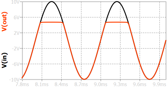
In the above figure, a voltage source V2 adds 4V in series with the diode. This means that the diode will turn on when the diode's anode voltage is more than 4V. In this case, we know that if the diode turns on, the voltage is fixed to the diode's cathode voltage. So, beyond 4V, the output is fixed to 4V. Below 4V, the diode turns off, and the output follows the input.

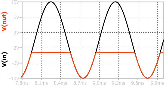
A voltage source with a negative value (e.g., -4V) can be added in series with the diode to shift the trigger voltage below zero voltage. In this case, the diode is turned off only when the anode exceeds the cathode voltage of -4V. Whenever the diode is turned on, the voltage is fixed to a cathode voltage of -4V. We can see that the positive part of the output waveform is clipped, so it is called a positive clipper.
Shunt negative clipper circuit with bias

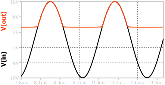
In the provided diagram, a voltage source, V2, introduces an additional 4V in series with the diode. Consequently, the diode will become conductive when the voltage at its cathode is below 4V. Once the diode turns on, the output remains fixed at the diode's cathode voltage. So, below 4V, the output is fixed at 4V. Conversely, when the voltage is above 4V, the diode turns off, and the output voltage equals the input voltage.

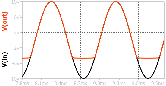
A negative voltage with the diode can be added in series to shift the trigger po\int below 0V. In this way, the output follows the input above -4V volts and the output remains at -4V when the input is below -4V.
Dual clipper circuit
Dual clipper circuits are employed when it is necessary to eliminate specific portions from both the positive and negative halves of a signal. In the positive half of the input cycle, diode D becomes forward-biased due to the supply voltage while simultaneously being in a reverse-biased state due to the battery potential V. Simultaneously, diode D is in a reverse-bias condition due to both the supply voltage and the battery potential V. As long as the battery voltage remains below the supply voltage, diode D remains in a reverse-biased state, and D is already in a reverse-biased condition. Consequently, the signal is obtained at the output.
However, when the supply voltage exceeds the battery potential, diode D becomes forward-biased. This results in no further signal for the positive half, as the signal is now effectively clipped.
In the negative half of the input cycle, diode D is reverse-biased due to both the supply voltage and the battery potential. The specific characteristics of dual clipper circuits allow for controlled clipping of both positive and negative portions of the input signal based on the relationships between supply voltage, battery potential, and diode states.
Difference between series and shunt clipper

To understand the difference between series and shunt clipper, let's observe the flat region and sine-wave region. The flat region in the series clipper circuit exactly equals the voltage source or ground. The sine-wave region does not follow the input waveform exactly. The flat region in the shunt clipper circuit is not exactly the voltage source or ground. It is 0.7V away from the voltage source. The sine-wave region is exactly equal to the input voltage in the shunt clipper circuit.