Closed loop current sensing
Current sensors find broad use in many applications. One common method is resistive current sensing, which involves measuring the voltage drop across a shunt resistor to figure out the current. However, this shunt resistor approach lacks electrical isolation and isn't very power-efficient, particularly for measuring high currents. Another commonly used method involves the Hall effect. A Hall effect current sensor is safer because it electrically isolates the sensor from the current being measured. This approach also doesn't waste as much power as using a shunt resistor, as seen in resistive current sensing methods. These all are open-loop methods which are simple, and cost-effective but not very accurate and reliable.
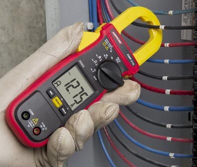
For high accuracy and stability across temperatures, closed-loop current sensing is preferred, providing accuracy levels up to ppm. The zero flux method is the most common form of closed-loop current sensing. In this article, we will discuss about closed loop method of current sensing.
Zero flux method
Traditional current measurement methods involve using current transformers or shunt resistors, which can have limitations in accuracy, linearity, and power loss. Zero-flux current sensing aims to overcome these limitations by minimizing the impact of magnetic flux on the measured current, thus improving accuracy and reducing the potential for interference.
Principle of zero flux method
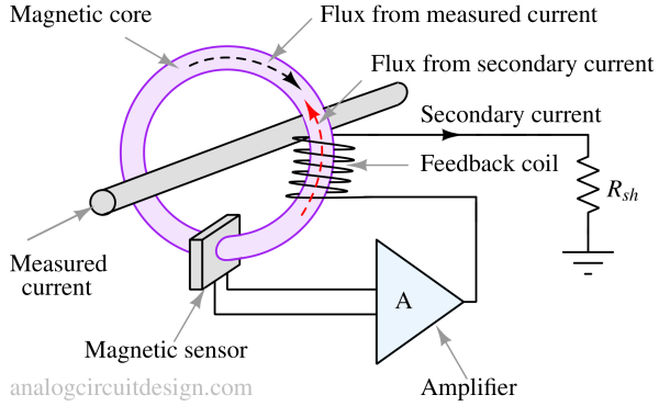
A magnetic flux (Φ) is produced inside the magnetic core by the electric current flowing in the conductor being measured. Since there is a non-zero magnetic flux inside the magnetic core, the magnetic sensor reads a non-zero magnetic field. This leads the very high gain amplifier to supply a current through the feedback coil such that the flux from the secondary current tries to cancel the flux from the measured current. As a result of the cancellation, there is zero flux (very less) inside the magnetic core. This secondary current passes through Rsh and produces a voltage drop proportional to the secondary current. The secondary current is proportional to the flux from the measured current, which is proportional to the measured current.The Rsh's voltage drop is measured using a precision instrumentation amplifier to capture the information of current.
Why a magnetic core is needed for a current sensor to work?
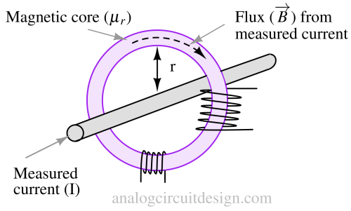
Let's imagine there's no magnetic core and only an air gap in the measuring coil. When you're at a distance "r" from a really long, straight wire that has an electric current "I" flowing through it, the magnetic field at that po\int is given by:
$$\overrightarrow{B}=\cfrac{\mu_o\mu_rI_o}{2\pi{}r}$$
μr=1 for air, so the magnetic field at a 2-cm radius and at 1 A current is :
$$\overrightarrow{B}=\cfrac{4\pi{}\times{}10^{-7}\times{}1\times{}1}{2\pi{}\times{}2\times{}10^{-2}}=0.01\text{mT}$$
The typical sensitivity of a hall-effect sensor is 10mV/mT. So, 0.01mT will generate 0.1mV of voltage for 1A of current. 0.1mV is a small voltage and 1A current is a high current. For currents in the mA range, the output voltage out of a hall-effect sensor will be μV range which is an even smaller voltage and hard to amplify even with the best of the precision amplifiers.
To make the sensor more sensitive, we can use a magnetic core to concentrate and direct the magnetic field created by the current. The core provides a high-permeability path for the magnetic field and intensifies it. Inside the core, the magnetic field can be thousands of times stronger than what the same current generates in air because of μr > 1000 (e.g., iron).
Types of magnetic sensors in zero flux method
Based on the magnetic sensor used, the zero flux method can be classified into three types :
Winding detection (AC measurement only)
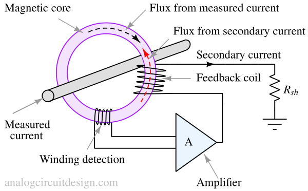
As shown in Fig 2, the magnetic sensor is wire windings. These wire windings are capable of measuring AC magnetic flux only. This means only AC currents can be measured using this method.
Hall element detection (AC/DC measurement)
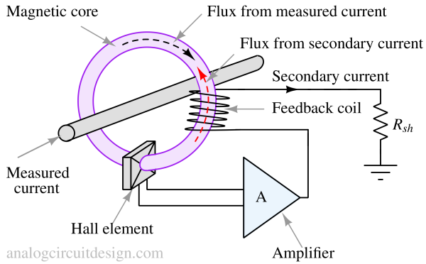
As shown in Fig 2, the magnetic sensor is a Hall element. The Hall sensors are capable of measuring AC as well as DC magnetic flux. This means that both DC/AC currents can be measured using this method.
The significant advantage of Hall element detection is wide bandwidth and low noise. However, the temperature stability and accuracy are better in Flux gate detection.
Flux gate detection (AC/DC measurement)
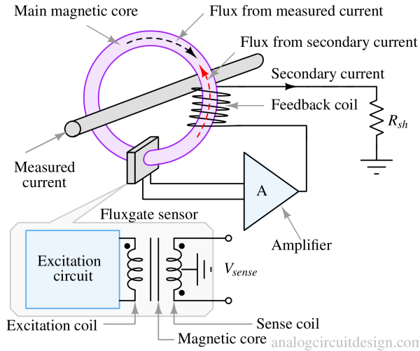
As shown in Fig 3, the magnetic sensor is a Flux gate sensor. The Flux gate sensors are capable of measuring AC as well as DC magnetic flux. This means that both DC/AC currents can be measured using this method.
The excitation coil induces a voltage (Vsense) in the sense coil. With no external magnetic field (flux from measured current), both ends of the sense coil induce an equal voltage, and Vsense is zero. With the external field influencing the magnetic core, both ends of the sense coil have different voltages. So, there is non-zero Vsense voltage. If the external flux is too high, there is no control over the sense coil by excitation coil, and Vsense will be zero.
The linearity achieved in the flux gate method is better than any other method since the core operates in the linear region of the B-H curve. This is because the negative feedback cancels the flux from the measured current.
The following operations support broad bandwidth: utilize the Fluxgate and amplifier for the low-frequency ranging from DC and with the feedback winding in the high-frequency range.
Further reading and References
- S. Ziegler, R. C. Woodward, H. H. -C. Iu and L. J. Borle, "Current Sensing Techniques: A Review," in IEEE Sensors Journal, vol. 9, no. 4, pp. 354-376, April 2009, doi: 10.1109/JSEN.2009.2013914.
- M. F. Snoeij, V. Schaffer, S. Udayashankar and M. V. Ivanov, "An integrated fluxgate magnetometer for use in closed-loop/open-loop isolated current sensing," ESSCIRC Conference 2015 - 41st European Solid-State Circuits Conference (ESSCIRC), Graz, Austria, 2015, pp. 263-266, doi: 10.1109/ESSCIRC.2015.7313877.