Color sensor
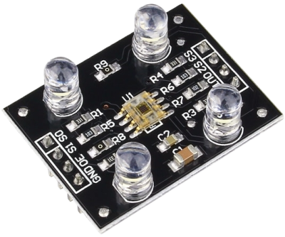
A color sensor is an electronic device that detects and measures colors in the surrounding environment. The most common types of color sensors are RGB (Red, Green, Blue) sensors, which use three photodiodes to measure the intensity of red, green, and blue light components. By combining the readings from these photodiodes, the color sensor can determine the overall color of the detected object. Some color sensors can measure light intensity at specific wavelengths in the electromagnetic spectrum. The unit of measurement for such sensors is typically nanometers (nm), representing the wavelength of light being detected. Modern color sensors/image sensors use pinned photodiodes (PPDs) in their sensor arrays for enhanced performance.

RGB color model
The RGB color model, also known as the additive color model, is widely used in digital imaging, computer graphics, and electronic displays It is based on the idea that any color can be created by combining varying intensities of three primary colors: Red (R), Green (G), and Blue (B). Adjusting the intensity of these three primary colors can achieve a wide range of colors.
In the RGB model, each color is represented by three numerical values, typically ranging from 0 to 255, where 0 represents no intensity (absence of the color), and 255 represents full intensity. The three components combine to form a specific color. For example:
- Pure Red: (255, 0, 0) - Full intensity of red with no green and blue.
- Pure Green: (0, 255, 0) - Full intensity of green with no red and blue.
- Pure Blue: (0, 0, 255) - Full intensity of blue with no red and green.
Block diagram of a color sensor unit

Mosaic pattern of sensor
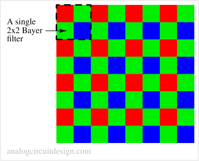
The mosaic pattern in con\text of color sensors refers to the arrangement of color filters (aka photodiodes) used in sensors to detect and distinguish different colors. The most common mosaic pattern used in color sensors is the Bayer filter array, named after its inventor, Bryce Bayer.
The Bayer filter array is a pattern of red, green, and blue filters placed over individual pixels in an image sensor. The arrangement is typically in a 2x2 repeating pattern, where each group of four pixels has one red filter, one blue filter, and two green filters. Green is used twice as it is the color the human eye is most sensitive to.

When light passes through the Bayer filter array, each pixel records only one color component, and the missing color information must be estimated by interpolating through the adjacent pixel's data. The sensor and the image processing pipeline combine the values from neighboring pixels to calculate the missing color information and create a full-color image.
Pinned photodiode

Problems with regular photodiode:
- If a brightly illuminated pixel in a regular photodiode is later dimly illuminated, carriers from the brightly illuminated period may continue to transfer out of the n+ region in subsequent frames. This is called the lag effect, leading to the comet tail effect in older CCD cameras. The lag is related to subthreshold conduction in MOSFETs and can be substantial.
- The kT/C noise in regular photodiodes was high enough to limit the low-light imaging.
- Regular photodiodes' blue light sensitivity (quantum efficiency) was very low.
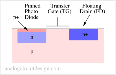
The pinned photodiode was introduced to overcome these limitations. It is designed with an additional "pinned surface layer," which transfers all the charges from a brightly illuminated period leaving no/negligible charges behind, solving the lag problem.
Pinned photodiode (PPD) sensors are widely used today in high-performance imaging due to their low readout noise, high conversion gain, and low dark current.
Note: The pinned photodiode is different from the PIN diode.
CMOS active pixel image sensor

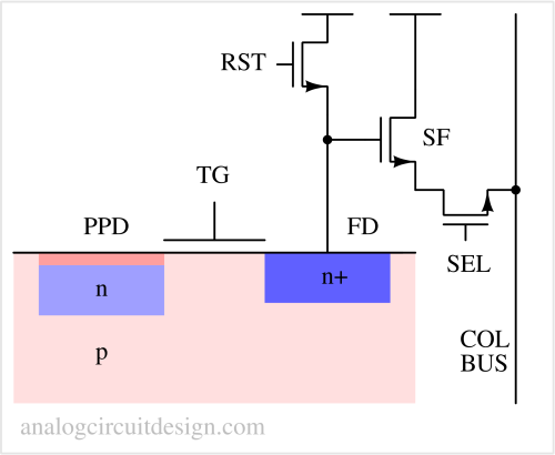
The signal charge collected by the pixel photodetector is transferred to a floating diffusion (FD) whose potential is monitored by a source-follower (SF) within the pixel. FD is reset by the transistor reset signal (RST) before the transfer, and the source-follower is connected to the column bus line (COL BUS) using a row-select transistor (SEL).