DC motor
A DC motor is an electrical machine that converts electrical energy into mechanical energy. Inside a DC motor, the input electrical energy, which is in the form of direct current (DC), gets transformed into mechanical rotation in the presence of a stationary magnetic field.
Working principle of DC motor
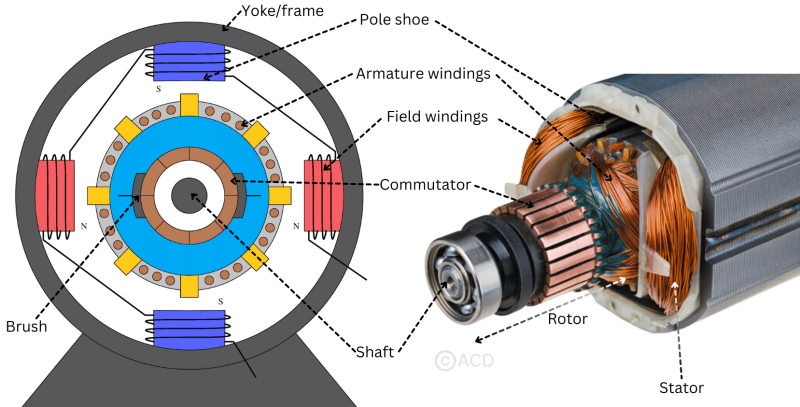
At its core, a DC motor operates on the principle of electromagnetism. It consists of several essential components, including a stator (the stationary part) and a rotor (the rotating part). The stator is typically a permanent magnet or contains field windings that generate a magnetic field when an electrical current flows through them. On the other hand, the rotor, connected to an external circuit, experiences a force when interacting with the magnetic field produced by the stator, leading to rotational motion.

When an electric current (i) flows through a coil (Armature winding) within a fixed magnetic field, it generates a magnetic force, resulting in a torque that rotates the DC motor. This magnetic force, denoted as F, operates perpendicularly to both the wire and the magnetic field. To sustain the coil's rotation in a consistent direction, the commutator switches the current's direction every half revolution, ensuring the continuity of the torque. The magnetic field extends from the North Pole to the South Pole.
Parts of a DC motor
A DC motor is made from following parts :

Stator
The term "stator" originates from "stationary," denoting the static electrical components within a DC motor. The stator remains stationary and in case of brushed DC motor, it generates a fixed magnetic field encircling the rotor, prompting rotor movement upon voltage application. The stator includes:
- Yoke or frame
- Field windings (in case permanent magnets are not being used to generate the magnetic field)
- Poles
Rotor
The term "rotor" derives from "rotate" and represents the electrically movable component within a DC motor. It constitutes the rotating part of the motor that dynamically responds when voltage energizes the armature winding. Rotor consists of:
- Shaft
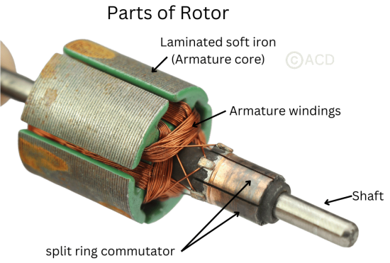
- Armature core and windings (in case of brushed DC motors)
- Magnets (in case of brush-less DC motors)
- Commutator

Armature of a DC motor
The armature is a part of an electric motor or generator that produces an electric current when it turns in a magnetic field. In some motors (e.g., brushed DC motors), the armature is coupled with the rotor shaft and responsible for generating torque. A generator is responsible for generating electromagnetic force (EMF). The armature can be used on the machine's stationary and rotating parts. Armatures are comprised of the core, the winding, the commutator, and the shaft.
The armature core, made from laminated low hysteresis silicon steel, serves the purpose of reducing magnetic losses. Assembled by interlocking layered steel sheets, it takes on a cylindrical shape. Inside this core, slots are constructed using the same material as the core itself.
Commutator of a DC motor
A commutator in a DC motor functions as a rotating electrical switch, switching the applied DC current to different armature winding when a angular motion is generated due to torque. The commutator arrangement is made in such a way that at the armature winding falling in the magnetic field always receive the current to produce torque.
Commutator has the form of a split ring. The ring is made from copper and split in 2 or more depending on the number of armature winding. The split segment is connected to the armature winding. Each split ring segment is insulated each other with insulator material like a Mica.
Brush of a DC motor
Brushes are attached to the commutator as a bridge to deliver the electrical energy from the supply circuit to the rotor. Brushes are usually made from Carbon or Graphite material. Brush remains stationary while the commutator rotates.
Yoke or Frame of DC motor
The yoke serves as an iron frame shielding and safeguarding both the rotor and stator components. It also provides structural support for the armature. Additionally, it houses the magnetic poles, field windings, and the pole, facilitating the creation of magnetic fields necessary for the rotor's operation.
Poles of DC motor
Poles are responsible for generating the magnetic field. These poles consist of two main components: the Pole Core and the Pole Shoes.
The primary role of the pole core is to house the essential field winding responsible for creating flux. It guides this flux across the air gap towards the armature core and subsequently to the next pole. Meanwhile, the pole shoe serves to increase the surface area of the armature core, allowing it to intercept the flux, thereby generating a larger induced electromotive force (e.m.f). This is accomplished by designing the pole shoe with a specific shape tailored for this purpose.
Types and classification of DC motors
DC motors come in various types tailored to suit specific applications. From brushed to brush-less variants, and series-wound to shunt-wound constructions, the diversity in design caters to distinct operational requirements concerning torque, speed, efficiency, and control mechanisms.
Types of DC motors based on presence of brush :
-
DC motor
- Brushed DC motor
- Brushless DC motor
Classification of DC motors based on how the stator and rotor connections are made :
-
DC motor
- Permanent magnet
- Separately excited
-
Self excited
- Shunt excited
- Series excited
-
Compound excited
- Cumulative compound
- Differential compound
Applications of DC motors
The versatility of DC motors renders them indispensable across industries. In automotive engineering, they power electric vehicles, window regulators, and windshield wipers. They drive conveyor belts in manufacturing units, facilitate precise movements in robotics, and propel drones and unmanned aerial vehicles. Their functionality extends to household appliances like vacuum cleaners and power tools, contributing silently yet significantly to our daily lives.