Demultiplexers (DEMUX)
A demultiplexer, also referred to as a Demux or data selector, functions as a digital circuit receiving a single input signal and logically connecting it to a specific output line among several, decided by control signals. Its fundamental role stands in contrast to that of a multiplexer, as the latter selects one from numerous inputs and logically connects it to a single output.
1-to-2 Demultiplexer
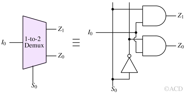
In 1-to-2 Demux, an input labeled I0 and a select signal labeled S0 are provided. This 1 x 2 demultiplexer yields two outputs, namely Z1 and Z2. When S0 is low, the Z0 is assigned the values of I0 while Z1 is kept low. When S0 is high, Z1 is assigned the values of I0 while Z0 is kept low. The following truth table summarizes the logic states of 1-to-2 Demux:
Truth table of 1-to-2 Demux
| Input | Output | |
|---|---|---|
| S0 | Z1 | Z0 |
| 0 | 0 | I0 |
| 1 | I0 | 0 |
Circuit diagram and symbol of 1-to-2 Demux

1-to-4 Demultiplexer
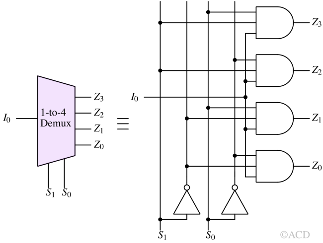
The 1 x 4 De-multiplexer consists of four outputs designated as Z0, Z1, Z2, and Z3, two selection lines denoted as S0 and S1, and a solitary input referred to as I0. The association between an input and an output is established according to the specific combination of the selection lines S0 and S1. Below are the circuit diagram and truth table for the 1 x 4 demultiplexer.
Truth table of 1-to-4 Demux
| Input | Output | ||||
|---|---|---|---|---|---|
| S1 | S0 | Z3 | Z2 | Z1 | Z0 |
| 0 | 0 | 0 | 0 | 0 | I0 |
| 0 | 1 | 0 | 0 | I0 | 0 |
| 1 | 0 | 0 | I0 | 0 | 0 |
| 1 | 1 | I0 | 0 | 0 | 0 |
Circuit diagram and symbol of 1-to-4 Demux

1-to-8 Demultiplexer
The 1 to 8 De-multiplexer features eight outputs identified as Z0 through Z7, three selection lines denoted as S0, S1, and S2, and a single input referred to as I0. The routing of the input signal to one of the outputs is determined by the specific combination of inputs present at the selection lines S0, S1, and S2.
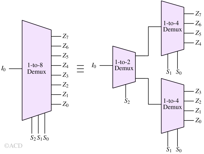
Traditionally, the 1-to-8 Demultiplexer can be constructed using NOT gates and AND gates. However, to showcase the construction of higher order demultiplexers using lower order demultiplexers, an illustration of a 1-to-8 demultiplexer utilizing two 1-to-4 and one 1-to-2 demultiplexer is presented below.
Circuit diagram and symbol of 1-to-8 Demultiplexer

Using two 1 x 4 demultiplexers and one 1 x 2 demultiplexer allows the construction of higher-order 1 x 8 demultiplexers. Two selection lines, S0 and S1, are connected to the two 1 x 4 demultiplexers, while one selection line is linked with the 1 x 2 demultiplexer.
To achieve 8 data outputs, we utilize two 1 x 4 demultiplexers. Additionally, the 1 x 2 demultiplexer generates two outputs. Consequently, the outputs from the 1 x 2 demultiplexer must serve as inputs to the 1 x 4 demultiplexer to produce the final output.
Demultiplexer applications
Demultiplexers find application across diverse digital uses such as memory address decoding, communication systems, and digital signal processing. Their versatility extends to distributing a solitary input signal to multiple outputs or linking multiple devices to a singular output line.