Digital encoder and Priority Encoder
An encoder is a digital circuit that transforms M (< 2N) digital inputs into distinct code outputs (represented by N-bits), symbolizing the input's position. Usually, 2N > M > N. It finds extensive application in digital systems, facilitating the conversion of many parallel input lines into less output lines. 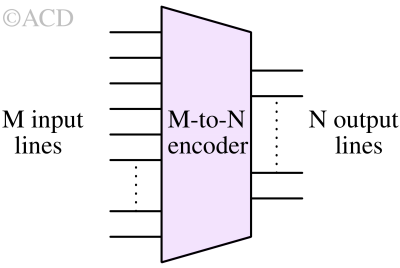
Common types of encoder
- 4 to 2 Encoder
- Octal to Binary Encoder (8 to 3 Encoder)
- Decimal to BCD Encoder
- Priority Encoder
4 to 2 Encoder
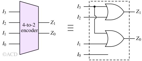
The 4-to-2 Encoder is comprised of four inputs, namely I0, I1, I2, and I3, along with two outputs denoted as Z0 and Z1. So, it has 16 possible input combinations while only 4 possible output combinations. So, it is not possible to map every input combination to a unique output combination. Therefore a limitation at the input has to be set. At any instant, only one of the four inputs can be set as '1' to obtain the corresponding binary code at the output. If any two or more inputs are set to '1', any one of the four combinations of output may come. The diagram below illustrates the logic symbol representing the 4-to-2 encoder.
| Inputs | Outputs | ||||
|---|---|---|---|---|---|
| I3 | I2 | I1 | I0 | Z1 | Z0 |
| 0 | 0 | 0 | 1 | 0 | 0 |
| 0 | 0 | 1 | 0 | 0 | 1 |
| 0 | 1 | 0 | 0 | 1 | 0 |
| 1 | 0 | 0 | 0 | 1 | 1 |
The logic expression for the output Z1 and Z0 is:
$$Z_1=I_3+I_2$$
$$Z_0=I_3+I_1$$
We can observe that input patterns (I3,I2,I1,I0=1,0,0,0) and (I3,I2,I1,I0=0,1,1,0) produces same output (Z1,Z0=1,1). The former pattern has a only single input as 1 while in the later pattern, we have two inputs as 1. Since the output is the same for both input patterns, it is hard to determine which input state caused it. There are some scenarios where only one input line will be high at any instant (positional encoders). However, due to noise or glitches, it can accidentally happen that 2 input lines are set together.
To get rid of this ambiguity priority encoders are used.
Octal to Binary Encoder (8 to 3 Encoder)
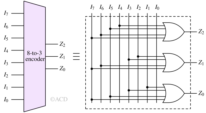
The 8-to-3 Encoder, also known as the octal-to-binary encoder, is composed of 8 inputs labeled I0 to I7 and 3 outputs named Z2, Z1, and Z0. Each input line is mapped to a unique 3-bit number, the three outputs produce the respective 3-bit binary code. The diagram below illustrates the logic symbol of the octal-to-binary encoder.
| Inputs | Outputs | |||||||||
|---|---|---|---|---|---|---|---|---|---|---|
| I7 | I6 | I5 | I4 | I3 | I2 | I1 | I0 | Z2 | Z1 | Z0 |
| 0 | 0 | 0 | 0 | 0 | 0 | 0 | 1 | 0 | 0 | 0 |
| 0 | 0 | 0 | 0 | 0 | 0 | 1 | 0 | 0 | 0 | 1 |
| 0 | 0 | 0 | 0 | 0 | 1 | 0 | 0 | 0 | 1 | 0 |
| 0 | 0 | 0 | 0 | 1 | 0 | 0 | 0 | 0 | 1 | 1 |
| 0 | 0 | 0 | 1 | 0 | 0 | 0 | 0 | 1 | 0 | 0 |
| 0 | 0 | 1 | 0 | 0 | 0 | 0 | 0 | 1 | 0 | 1 |
| 0 | 1 | 0 | 0 | 0 | 0 | 0 | 0 | 1 | 1 | 0 |
| 1 | 0 | 0 | 0 | 0 | 0 | 0 | 0 | 1 | 1 | 1 |
$$Z_2=I_4+I_5+I_6+I_7$$
$$Z_1=I_2+I_3+I_6+I_7$$
$$Z_0=I_1+I_3+I_5+I_7$$
Decimal to BCD encoder
The typical decimal-to-binary encoder comprises 10 input lines and 4 output lines. Each input line represents a decimal digit, and the 4 outputs generate the Binary Coded Decimal (BCD) code. This encoder takes decoded decimal data as input and converts it into BCD output, which becomes accessible via the output lines. The diagram below depicts the logic symbol of the decimal-to-BCD encoder.
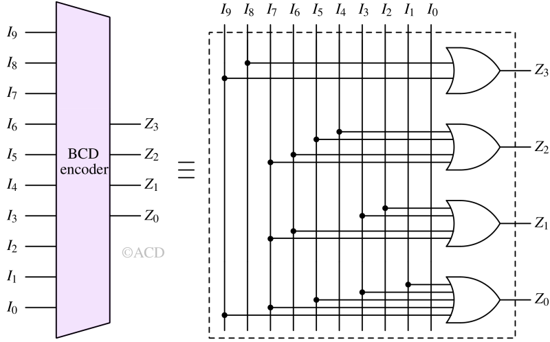
Table 3 : Truth table of 8 to 3 encoder
| Input | Output | ||||||||||||
|---|---|---|---|---|---|---|---|---|---|---|---|---|---|
| I9 | I8 | I7 | I6 | I5 | I4 | I3 | I2 | I1 | I0 | Z3 | Z2 | Z1 | Z0 |
| 0 | 0 | 0 | 0 | 0 | 0 | 0 | 0 | 0 | 1 | 0 | 0 | 0 | 0 |
| 0 | 0 | 0 | 0 | 0 | 0 | 0 | 0 | 1 | 0 | 0 | 0 | 0 | 1 |
| 0 | 0 | 0 | 0 | 0 | 0 | 0 | 1 | 0 | 0 | 0 | 0 | 1 | 0 |
| 0 | 0 | 0 | 0 | 0 | 0 | 1 | 0 | 0 | 0 | 0 | 0 | 1 | 1 |
| 0 | 0 | 0 | 0 | 0 | 1 | 0 | 0 | 0 | 0 | 0 | 1 | 0 | 0 |
| 0 | 0 | 0 | 0 | 1 | 0 | 0 | 0 | 0 | 0 | 0 | 1 | 0 | 1 |
| 0 | 0 | 0 | 1 | 0 | 0 | 0 | 0 | 0 | 0 | 0 | 1 | 1 | 0 |
| 0 | 0 | 1 | 0 | 0 | 0 | 0 | 0 | 0 | 0 | 0 | 1 | 1 | 1 |
| 0 | 1 | 0 | 0 | 0 | 0 | 0 | 0 | 0 | 0 | 1 | 0 | 0 | 0 |
| 1 | 0 | 0 | 0 | 0 | 0 | 0 | 0 | 0 | 0 | 1 | 0 | 0 | 1 |
$$Z_3=I_9+I_8$$
$$Z_2=I_7+I_6+I_5+I_4$$
$$Z_1=I_7+I_6+I_3+I_2$$
$$Z_0=I_9+I_7+I_5+I_3+I_1$$
Priority encoder
A priority encoder, similar to a basic encoder, converts numerous binary inputs into fewer outputs. Its output reflects the binary index of the most significant activated line. Unlike the basic encoder, if multiple inputs are active simultaneously in a priority encoder, the one with the highest priority will decide the output. This eliminates the ambiguity we face in normal encoders. While it can manage all potential input combinations, it requires additional logic, making it beneficial over a basic encoder but at the expense of increased complexity.
A 4-to-2 priority encoder
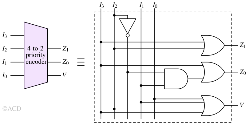
A 4-to-2 priority encoder has 4 inputs named I3, I2, I1, and I0, along with 2 outputs labeled Z1 and Z0. Within this setup, I3 is assigned the highest priority, while I0 is assigned the lowest. In this scenario, if multiple inputs are simultaneously high '1', the output will represent the (binary) code of the input with the highest priority. Below is the truth table illustrating the functionality of the priority encoder. Another output is added called 'V' (Valid) to detect all input zero states.
Table 4: Truth table of 4 to 2 priority encoder
| Inputs | Outputs | |||||
|---|---|---|---|---|---|---|
| I3 | I2 | I1 | I0 | Z1 | Z0 | V |
| 0 | 0 | 0 | 0 | X | X | 0 |
| 0 | 0 | 0 | 1 | 0 | 0 | 1 |
| 0 | 0 | 1 | X | 0 | 1 | 1 |
| 0 | 1 | X | X | 1 | 0 | 1 |
| 1 | X | X | X | 1 | 1 | 1 |

$$Z_1=I_3+I_2$$
$$Z_0=I_3+\bar{I_2}I_1$$
$$V=I_3+I_2+I_1+I_0$$
Verilog code for priority encoder
module priority_encoder_4_to_2(en, Din, Dout);
input en;
input [3:0] Din;
output reg [1:0] Dout;
always @ (Din,en)
begin case (Din)
4'b00000001: Dout = 2'b000;
4'b0000001x: Dout = 2'b001;
4'b000001xx: Dout = 2'b010;
4'b00001xxx: Dout = 2'b011;
default: Dout = 2'bxx;
endcase
end
endmodule
module priority_encoder_8_to_3(en, Din, Dout);
input en;
input [7:0] Din;
output reg [2:0] Dout;
always @ (Din,en)
begin case (Din)
8'b00000001: Dout = 3'b000;
8'b0000001x: Dout = 3'b001;
8'b000001xx: Dout = 3'b010;
8'b00001xxx: Dout = 3'b011;
8'b0001xxxx: Dout = 3'b100;
8'b001xxxxx: Dout = 3'b101;
8'b01xxxxxx: Dout = 3'b110;
8'b1xxxxxxx: Dout = 3'b111;
default: Dout = 3'bxxx;
endcase
end
endmodule