Flip-Flop and Latch
Flip-flops and latches serve as essential components in digital electronics, enabling the storage and transfer of binary data. Latches, being simpler, are foundational elements. In contrast, flip-flops provide enhanced control and synchronization with glitch immunity owing to their edge-triggered functionality. Flip-flops find extensive application in synchronous digital systems where exact timing and stability are imperative. Conversely, latches are commonly employed in less complex scenarios where synchronization holds less importance.
Latches
- Level-Triggered - Latches are level-triggered, meaning they are sensitive to the input level. They constantly monitor their inputs and change their output whenever there's a change in the input signal level.
- Unconditional State Change - Latches can change state whenever the input changes, potentially leading to glitches or erratic behavior if the input changes at the wrong time.
- Races - In some cases, latches can experience race conditions (JK Latch), where the output is sensitive to the order of input changes.
- Common Types - SR latch, D latch, gated latch.
Flip-flops
- Edge-Triggered - Flip-flops are edge-triggered devices. They change state only at the rising or falling edge of a clock signal, providing better synchronization.
- Synchronized State Change - Due to their edge-triggered nature, flip-flops ensure that state changes occur precisely at the specified clock edge, reducing glitches and potential race conditions.
- Stable Outputs (no Race condition) - Once triggered, a flip-flop's output remains stable until the next clock edge.
- Common Types - D flip-flop, JK flip-flop, T flip-flop.

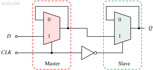
Flip-flops are constructed using a master-slave configuration of latches. To understand this, let's take a simple example of a negative edge-triggered D flip-flop. Since it has only one input it is easier to understand.
The master latch becomes transparent (enabled) capturing the input when the clock is high. At the same time, the slave is disabled which is holding the previous value. When the clock is low, the slave latch becomes transparent and locks the state captured by the master. At the same time, the master is disabled (becomes opaque) so input is not going to affect its latched output. The output of the slave latch is the data captured. The data handover from master to slave occurs during the transition from high clock level to low clock level, providing negative edge control to the clock.