Full wave rectifiers
A full wave rectifier converts both positive and negative cycles of input AC waveform into positive pulsating DC waveform. It is better than a half-wave rectifier because the ripple voltage is lesser and utilizes both AC input's positive and negative cycles.
Circuit implementation of full wave rectifier
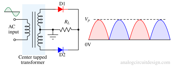
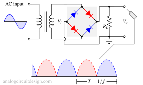
The center-tapped transformer has a middle tap, and two diodes are connected to each end of the secondary coil. For a non-center-tapped transformer, all four diodes are connected directly.
Center tapped transformer based full wave rectifier

With the help of a center-tapped transformer and two diodes, a full wave rectifier can be made.
When the primary side is positive, the secondary side's diode D1 turns on. When the primary side is negative, the secondary side's diode D2 turns on. In both cases, the direction of the current is into the load (RL). So, the output voltage will always be positive irrespective of the input AC voltage. This is how center tapped full wave rectifier works.
Full wave bridge rectifier
It's not always possible to get a center-tapped transformer. Also, the power is half of the input AC power for each cycle to maintain the same voltage level in a center-tapped transformer. So, a bridge rectifier maintains the same power level for positive and negative cycles.

The bridge rectifier has four diodes. A pair of diodes (shown in red) turns on in the positive cycle. Another pair (shown in blue) turns on in the negative half-cycle. This ensures the current flows in the same direction in positive and negative half cycles.
More about bridge rectifiers.
RMS and Average voltage of full-wave rectifiers
The RMS (root-mean-square) and Average voltage of full-wave rectifiers are listed below:
Average of full wave rectifier
$$V_{avg}=V_{dc}=\cfrac{\int_{0}^{T}V_{out}.dt}{T}=\cfrac{\int_{0}^{T}\Big|V_p.sin\left(\cfrac{2\pi{}}{T}t\right)\Big|.dt}{T}$$
$$\implies{}V_{avg}=\cfrac{2V_p}{\pi}$$
RMS of full wave rectifier
$$V_{rms}=\sqrt{\cfrac{\int_{0}^{T}V_{out}^2.dt}{T}}=\sqrt{\cfrac{\int_{0}^{T}V_p^2\sin^2\left(\cfrac{2\pi{}}{T}t\right).dt}{T}}$$
$$V_{rms}=\cfrac{V_p}{\sqrt{2}}$$
Form factor of full-wave rectifier
$$FF=\cfrac{V_{rms}}{V_{avg}}=\cfrac{V_p/\sqrt{2}}{2V_p/\pi{}}=1.11$$
We have explained more about the form factor in the Half wave rectifier article.
Ripple factor of full-wave rectifier
Ripple factor (γ) for a full wave rectifier,
$$\gamma{}=\sqrt{FF^2-1}=\sqrt{1.11^2-1}=0.48$$
For a full-wave rectifier, this value comes out to be 0.48. This is much better than a half-wave rectifier which has a ripple factor of 1.21
Advantages and disadvantages of full-wave rectifier
The advantages and disadvantages of full-wave rectifiers are listed below:
Advantages
- Lower ripple factor than half wave rectifier.
- Lower Vripple (half of that of half-wave rectifier)
- Utilizes both positive and negative half cycles of input AC waveform. Thus, it can deliver more RMS power.
Disadvantages
- Virtually no disadvantages in comparison to a half-wave rectifier.
- In real bridge rectifiers with discrete/passive diodes, the voltage drops across the diodes can cause significant power dissipation and heat generation. So, an active bridge rectifier is preferred over normal bridge rectifiers to save power.