Half wave rectifiers
Rectification is the process of converting an Alternating Current (AC) waveform into a Direct Current (DC) waveform.
The simplest rectifier is a half-wave rectifier. It allows only the positive part of the waveform to pass through.
Circuit implementation of half wave rectifier

Half wave rectifier consists of a diode that only allows the conduction of current in one direction. For the positive cycle, the diode is conducting. For the negative cycle, the diode becomes reverse biased, hence no conduction. The output resistor pulls down the output node to zero.
RMS and Average value of half-wave rectifiers
Average of half wave rectifier
$$V_{avg}=V_{dc}=\cfrac{\int_{0}^{T}V_{out}.dt}{T}=\cfrac{\int_{0}^{T/2}V_p.sin\left(\cfrac{2\pi{}}{T}t\right).dt}{T}$$
$$\implies{}V_{avg}=\cfrac{V_p}{\pi}$$
RMS of half wave rectifier
$$V_{rms}=\sqrt{\cfrac{\int_{0}^{T}V_{out}^2.dt}{T}}=\sqrt{\cfrac{\int_{0}^{T/2}V_p^2\sin^2\left(\cfrac{2\pi{}}{T}t\right).dt}{T}}$$
$$V_{rms}=\cfrac{V_p}{2}$$
Form factor of half-wave rectifiers
The Form Factor of the waveform is the ratio of the RMS value of the AC output voltage (Vrms) and the average value (rectified) of the pulsating DC output voltage (Vavg or Vdc). The ideal value of the Form factor is 0 (which happens for DC or rectangular waveforms). It signifies the deviation of peak from average value.
$$FF=\cfrac{V_{rms}}{V_{avg}}=\cfrac{V_p/2}{V_p/\pi{}}=1.57$$
Significance of Form factor

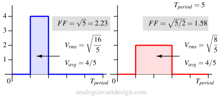
In the above figure, the average value of both waveforms is equal. However, the blue waveform has a higher RMS value because of the higher peak. So, a higher peak but the same average waveform will contribute more to the ripple at the output. Therefore, waveforms having higher form factor (i.e., Vrms/Vavg ) will have higher ripple.
Vrms reflects the variation in the output voltage's distance from the average. It is disproportionately impacted (due to second-order V2) by large deviations from the average value.
Vavg = |Vout|avg called average rectified value. For example, if the input is a sinusoid, the (unrectified) average value Vout,avg is 0. The FF will be undefined.
Ripple factor of half-wave rectifiers
The Ripple Factor (RF) measures the ripple content of the waveform. This is derived from the Form factor (FF). The ideal value of RF is 0. This is without adding any smoothing capacitors.
$$\gamma{}=\sqrt{\left(\cfrac{V_{rms}}{V_{avg}}\right)^2-1}=\sqrt{FF^2-1}$$
For a half-wave rectifier, this value comes out to be 1.21. A better rectifier would have a number lesser than 1.21.
To improve the ripple factor, usually smoothing capacitors are added to the output. We usually do not add smoothing capacitors to compare two different rectifiers.
Half wave rectifier with smoothing capacitor

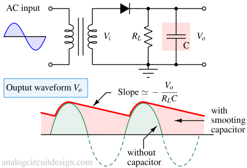
When the diode is forward-biased, the current flows from the load (RL) as well as the capacitor (C). The energy stored in the capacitor is then utilized when the diode is reverse-biased. The voltage across the capacitor drops at the rate set by the RL and the C.
$$V_{ripple}=\text{Slope}\times{}\text{Time interval}=\cfrac{V_o}{R_LC}\cfrac{1}{f}$$
Advantages and disadvantages of half-wave rectifier
Advantages
- Simple circuit connection so easy to use.
- The component count is less.
Disadvantages
- High ripple factor.
- Less efficiency.
- Harmonic contents are high.