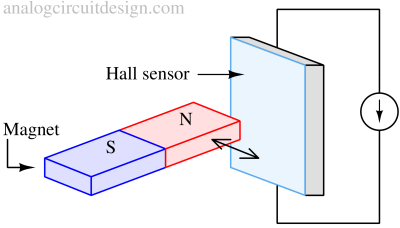
Hall effect sensors
A Hall effect sensor is a transducer that varies its output voltage in response to a magnetic field. It is a solid-state device, meaning it has no moving parts, making it extremely durable and reliable for sensing position, velocity, and current.
When a conductor or semiconductor (p-type : GaAs, InSb, InAs) with current flowing in one direction was introduced perpendicular to a magnetic field, a voltage could be measured at right angles to the current path. This voltage (called Hall voltage, VH) is proportional to the strength of the magnetic field being detected. The Hall-effect principle is named after physicist Edwin Hall.
Principle of Hall effect sensors
When an electric current flows through any material, the electrons within the current naturally move in an almost straight line, with the electricity creating its own magnetic field.
The magnetic field created by the electrons interacts with the external magnetic field being measured and a force is applied on the electrons which leads to deviation from a straight line path.
As a result of this new curved movement, more electrons are then present on one side of the material. A potential difference (or voltage) will then appear across the material at right angles to the magnetic field and the flow of the constant electric current.
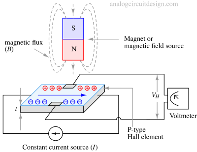
$$V_H=R_H\left(\cfrac{I}{t}\times{}B\right)$$
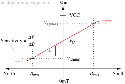
Linear or analog sensors give a continuous voltage output that increases with a strong magnetic field and decreases with a weak magnetic field. In linear output Hall effect sensors, as the strength of the magnetic field increases, the output signal from the amplifier will also increase until it begins to saturate by the limits imposed on it by the power supply. Any additional increase in the magnetic field will not affect the output but drive it more into saturation.
Hall effect sensor
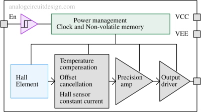
A complete hall effect sensor comprises other supporting blocks which provide better functionality. Such circuits are :
- Power management block - maintains constant current across the hall element
- Non-volatile memory - maintains the trim data even after power down
- Precision amplifier - improves the sensitivity of the overall hall sensor by eliminating its offset.
- Enable/disable - It is an optional functionality to reduce power during power down.
Hall effect sensor detection mechanism
Head on detection
This requires the magnetic field to be perpendicular to the Hall effect sensor, with the magnet approaching the sensor straight on. Linear sensors detect the magnetic field's strength through the magnet's distance in this approach. When the magnetic field is nearer, the stronger it is, leading to a greater output voltage.
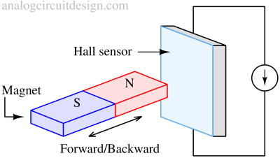
Sideways detection
This is when the magnet moves across the face of the Hall effect sensor in a sideways motion. This type of movement is particularly useful for counting rotational magnets or detecting how fast a motor is rotating.
