High pass filters
A high-pass filter is an electronic circuit that allows signals with frequencies higher than a certain cutoff frequency to pass through while attenuating signals with frequencies lower than the cutoff frequency. In other words, it passes high-frequency components of a signal and blocks or reduces low-frequency components.
Highpass filter transfer function
The general mathematical transfer function of a high-pass filter is :
$$\cfrac{v_o(s)}{v_i(s)}=\cfrac{\cfrac{s^2}{\omega{}_o^2}}{1+\cfrac{s}{\omega{}_oQ}+\cfrac{s^2}{\omega{}_o^2}}$$
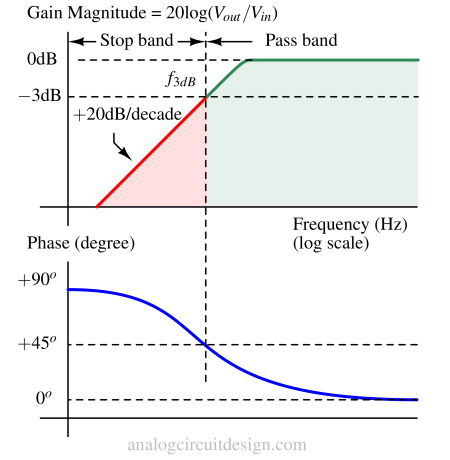
High-pass filters are used in audio systems to remove unwanted low-frequency noise or interference. For example, they can eliminate rumble and hum in audio recordings caused by vibrations or power supply fluctuations.
Passive high pass filter
Passive high pass filters use only passive elements like resistor, capacitor, and inductor to create high pass function. Some very common types of high-pass filter are listed below:
First order passive high pass filters
The first-order high pass filter has a slope of -20 dB per decade or -6 dB per octave. It is the simplest type of filter and is characterized by a single energy-storage element, such as a resistor (R) and capacitor (C). Technically, these are called first-order filters because the characteristic equation of these filters has order = 1.
RC high pass filter
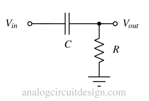
This type of filter consists of a resistor (R) and a capacitor (C) connected in series. The input signal is applied across the series combination, and the output is taken from the connection between the resistor and the capacitor. The cutoff frequency (fc) of an RC high-pass filter is determined by the values of the resistor and capacitor and can be calculated using the formula: fc = 1 / (2πRC). Signals with frequencies below the cutoff frequency are attenuated, while signals above the cutoff frequency pass through with minimal attenuation.
RL high pass filter
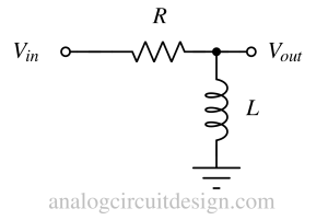
In an RL high-pass filter, a resistor (R) and an inductor (L) are connected in series. The input signal is applied across the series combination, and the output is taken from the connection between the resistor and the inductor. The cutoff frequency (fc) of an RL high-pass filter is determined by the values of the resistor and inductor and can be calculated using the formula: fc = R / (2πL). Similar to the RC filter, frequencies below the cutoff are attenuated, while frequencies above the cutoff pass through with minimal attenuation.
Second order passive high pass filters
Second-order passive high-pass filters have higher attenuation than first-order passive high-pass filters. These are called second-order high pass filters because the characteristic equation of the transfer function is of second order. These filters contain two reactive components. Both the reactive components could be capacitors or inductors or capacitor-inductor combinations.
RC-RC high pass filter
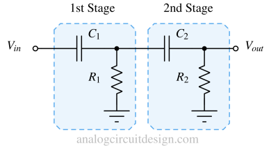
As shown in Fig 4, the first stage (R1,C1) provides an attenuation of 20dB/decade in the stop band. To achieve more attenuation, a second stage is added (R2,C2) which adds another -20dB/decade, raising the total attenuation in the stop band to -40dB/decade. The more stages are added, the attenuation becomes steeper. The transfer function of the RC-RC high pass filter (Fig 4) is mentioned below :

RLC high pass filter

A second-order high-pass filter can also be made using an RLC component. The cutoff frequency is ω = 1/√LC, after this the inductor becomes open and the capacitor becomes almost short allowing the signal to flow from Vin to Vout. The transfer function of the RLC high pass filter (Fig 5) is mentioned below:

Active high pass filter
Active high pass filter uses at least one active element like a transistor or an opamp to create a high pass function. Some very common types of high-pass filters are listed below:
First order active high pass filters
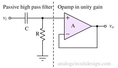
The passive high pass filter is cascaded with an opamp in unity gain to make an active high pass filter. This has the advantage of being isolated from the load applied at the Vout node. However, the gain is fixed at +1V/V. So, to obtain gain, a non-inverting amplifier with gain can be used in cascade.
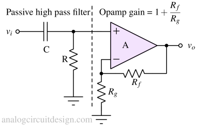
In Fig 7, the non-inverting amplifier is providing a gain of 1+Rf/Rg. So, the pass band has gain as well as the filter response won't change because of loading effect.
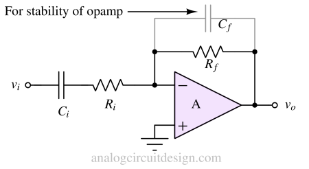
A high pass filter can be created using inverting amplifier topology also where the gain is -Rf/Ri in the pass band.
Second order active high pass filters
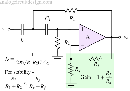
A second-order active high-pass filter is mentioned in Fig 9. More specifically it is a Sallen-key high-pass filter. It utilizes weak positive feedback to increase the Q-factor which improves to roll-off characteristics.
Transient response
When a high-pass filter is subjected to a sudden change in input, such as a step function, the output initially exhibits a sharp peak. The output might have overshoot or undershoot during this transient period before eventually settling to a steady-state value as shown in Fig 10.

Application of high pass filters
- Audio systems for noise reduction and speaker crossovers for sound optimization.
- Sensors and instrumentation to eliminate DC offsets and operate at different bias/ground conditions.
- Communication systems to filter out unwanted components.
- Image processing for edge detection.
- Biomedical signal processing to remove low-frequency drift.
- RF and microwave circuits for signal separation.
- Antenna designed to block low-frequency interference.
- Inertial navigation for acceleration isolation.
- Seismic data processing for noise reduction.