Brushless DC motor
Brushless DC motors (BLDC motors), as their name suggests, operate without brushes. Unlike brushed motors where brushes transmit current to rotor coils through a commutator, brushless motors have fixed coils on the stator, while the rotor consists of permanent magnets. In brushless motors, the coils remain stationary and do not rotate, eliminating the requirement for brushes and a commutator.
The mechanical rotation is achieved by electronic switching (without brushes), and the BLDC motor experiences no wear and tear throughout its lifespan, leading to higher reliability.

Construction of brushless DC motor
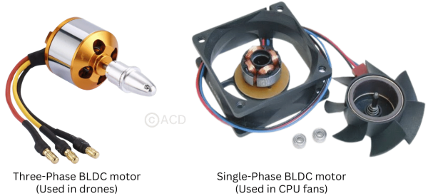
There exist various configurations of BLDC motors, distinguished by their stator windings, which may be single, dual, or three-phase. The predominant and most common design among BLDC motors is the three-phase setup, typically featuring a permanent magnet rotor.
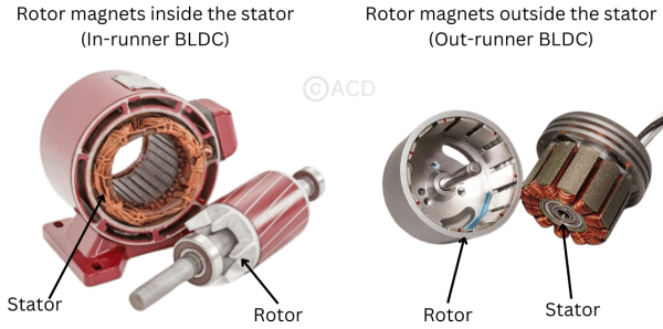
BLDC motors can be categorized as in-runner or out-runner types. In in-runner brushless motors, the permanent magnets reside within the electromagnets, while in out-runners, the permanent magnets are located outside the electromagnets. Despite these structural differences, both designs operate on the same fundamental principle but with varying configurations.

Stator
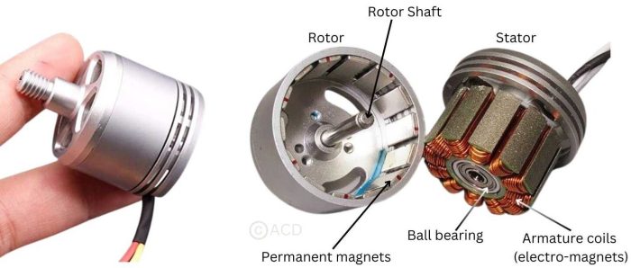
The brushless DC motor's stator is responsible for housing the electromagnets which generate the rotating magnetic field that spins the rotor. The stator comprises laminated steel stampings assembled to create a magnetic core. Coils of wire wound around this core are connected to the controller.
In the case of in-runner brushless motors, the stator encloses the rotor from outside. In the out-runner, the stator is inside the rotor.
Stator configurations can either be slotted or slotless. Slotless cores, which allow for high-speed motor operation due to their lower inductance, are a more expensive design as they require more coil turns.

Rotor
The rotor houses a permanent magnet featuring two to eight pairs of poles, alternating between south and north poles. The selection of magnetic material for the rotor is meticulously done to achieve the necessary magnetic field density. Rotor magnets can be of the ferrite or neodymium types. There are various core configurations for the rotor, including circular designs with magnets placed around the perimeter or circular shapes with rectangular magnets.
Hall sensor
Hall sensors play a crucial role in synchronizing the excitation of the stator armature by detecting the position of the rotor. Electronic control governs the commutation of BLDC motors, sequentially energizing the stator windings to drive rotor rotation. Before energizing a winding, the Hall sensor determines the rotor's position. Typically, BLDC motors are equipped with three Hall sensors embedded in the stator. As the rotor poles approach these sensors, each one produces both a low and high signal.
Working principle of a BLDC motor
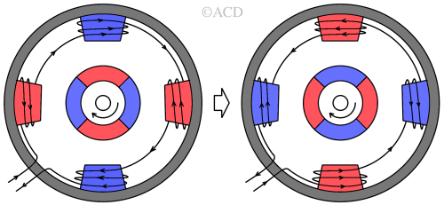
Brushless DC motors achieve continuous rotation by employing electric switches for current commutation. There are three types of BLDC motors: single-phase, two-phase, and three-phase. The number of phases is determined by the number of
stator windings. The single-phase and three-phase motors are the most commonly used.
For a single-phase BLDC motor, these switches typically form an H-bridge structure, while a three-phase BLDC motor utilizes a three-phase bridge structure.
Single Phase BLDC motor

The single-phase motor's stator features a single set of windings wound around four stator arms, leading to the formation of two pairs of electromagnetic poles when powered. Its uncomplicated design renders it smaller than a three-phase motor. Nonetheless, a single-phase BLDC motor is limited to rotating in only one direction. Hence, it finds widespread application in pump and fan systems due to this directional constra\int.
Three Phase BLDC motor

Three-phase motors comprise three sets of stator windings, enabling them to rotate both clockwise and counterclockwise. With three phases, these windings can be linked in two configurations: star and delta connections. Yet, the delta arrangement might be deemed inefficient for propelling a brushless DC motor, hence most BLDCs are star-connected. Although slightly costlier compared to a single-phase option, this choice is justified by enhanced control and smoother operation, providing significant compensation for the increased cost.
Torque constant
The equation of torque constant of a BLDC motor is :
$$K_{\tau{}}=\cfrac{60}{2\pi{}K_{v(RPM)}}$$
Where, Kτ is the torque constant in (N.m/A) and Kv is the speed constant in either rpm or rad/s.
Advantages of Brushless DC (BLDC) motors
- Absence of mechanical commutator and brushes to avoid wear :
Brushed DC motors utilize brushes and a commutator to supply current to a rotating armature within stationary magnets (stator). In contrast, Brushless DC motors employ a rotor, stator, rotation sensor, and control circuit. Unlike brushed motors, they regulate current through the stator coil electronically via semiconductor switching, eliminating the need for brushes and a commutator. Brushless DC motors are categorized into outer rotor and inner rotor types based on their rotor configuration. - High efficiency :
The high efficiency of brushless DC motors stems from the elimination of brushes. Brushes can generate electric arcs, reducing efficiency. A BLDC motor can convert a greater amount of electrical power into mechanical power compared to a brushed motor, largely due to the lack of brush friction. - High speed of operation in loaded and unloaded conditions :
Due to no friction due to the absence of brushes, the speed achieved can be very high. - Smaller motor geometry and lighter weight.
- Long life and higher reliability :
Brushed DC motors face wear issues due to constant brush and commutator contact, potentially leading to abrasion, dust, and sparking. In contrast, brushless DC motors lack this mechanical contact, ensuring extended motor life by avoiding wear-related problems. Opting for brushless DC motors reduces maintenance needs, extends equipment lifespan, and mitigates motor-related malfunctions. - Higher dynamic response because of low inertia:
Low inertia because the rotor does not carry the windings as brushed DC motors do. BLDCs are carrying the windings in the stator. - Less electromagnetic interference :
Brushed DC motors produce noise primarily because of the notable sparking during the contact switching between brushes and the commutator. Noise, considered a type of electromagnetic energy akin to other electrical signals, may disrupt other devices or electronic components if not adequately controlled. This interference can result in operational errors or reduced performance. - Low noise and quiet operation :
The distinct scraping sound in brushed motors might result from factors like resonance between parts, audible noise from friction, rotor movement causing vibration, wind noise from built-in fans, or electromagnetic forces impacting the stator core. - More reliable speed control than brushed DC motors :
In brushless DC motors, a Hall device (magnetic sensor) is used for feedback control and to determine the state of the motor. So, speed is regulated and can be changed easily despite having loads.