Input protection clamps
Input protection clamps absorb excess energy and protect sensitive circuits from damage when voltage levels spike above the device’s rated operating voltage. These input protection clamps are spread across a electronic system.
Sources of such voltage spikes in AC lines are :
- Lightning and Thunderstorm.
- Inductive load switching.
- Capacitor bank switching.
TVS (Transient voltage suppressor)
TVS diodes have a faster response time (in order of nanoseconds) and a high surge current absorbing ability, making them ideal against rapid transient voltage spikes. When a high transient voltage is applied across a TVS diode, the diode’s resistance changes from high to low very quickly, absorbing the transient current and protecting our important and delicate downstream devices.
Zener diode protection
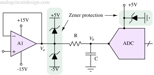
Zener diode is the simplest and cost effective way to protect sensitive circuits from overvoltage. If the input voltage (Va) is above 5.1V (reverse breakdown voltage of zener diode), then the bottom Zener takes all the current and clamps the voltage to 5.1V. If the input voltage (Va) is below -5.1V, the top Zener takes all the current and will clamp the voltage to -5.1V.
More about Zener diode in this article.
Zener protection for AC circuits
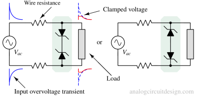
Back-to-back Zener diode configuration is common when there are 2 lines. There are 2 possible arrangements of Zener diodes which have same current-voltage relationship as mentioned in above figure.
MOV (Metal-oxide-varistors)
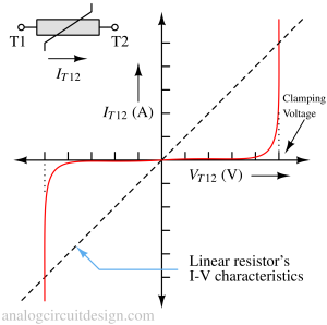
Varistors are bidirectional (symmetric) nonlinear passive devices that have an electrical behavior similar to back-to-back Zener diodes. The only extra advantage varistors provide is that these have very sharp resistance change and minimum bill-of-materials. These are time-invariant passive devices. It does not require zero current like SCRs to turn-off. They behave just like resistors but with rapidly changing resistance with voltage.
These are called metal-oxide varistors because metal oxides like ZnO and SiC are used to make these varistors and the grain-boundary interaction decides the critical properties of these varistors.
MOV construction
MOV Current-Voltage relationship
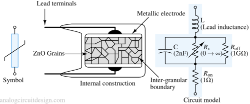
A popular element in fabrication of MOV is Zinc-Oxide (ZnO). Each ZnO grain of the ceramic acts as if it has a semiconductor junction at the grain boundary (inter-granular boundary). Since the electrical behavior results due to the boundary of each semiconductor like ZnO grain, the varistor is considered a “multi-junction” device composed of many series and parallel connections of grain boundaries. The grain size and its distribution decides the electrical behaviour of a varistor.
Thermal protection of MOVs
Usually MOVs are designed to handle rapid voltage transients for short duration. If MOVs are subjected to sustained voltage which is higher than the clamping voltage, then due to thermal runaway there could be irreversible catastrophic failure (smoke and burns) of the device. It is always important to put a fuse in series of MOV such that in case of sustained high current, the fuse blows away which can prevent MOV failure.
Connections with AC line
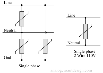
Specifications of varistors
Some specifications of MOVs are :
- Clamping voltage
- Rated RMS voltage
- Rated DC voltage
- DC standby current
- Varistor voltage at 1mA current
- Typical capacitance
SCR crowbar circuit
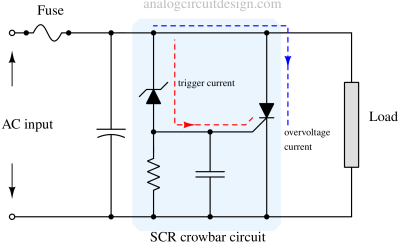
A crowbar circuit consists of a zener diode, resistor, capacitor and a SCR. The SCR is the main protection device which is trigger only when zener breakdown happens. When zener breakdown happens, it charges the RC network and triggers the SCR.
Applications
- Surge Protection Devices (SPD)
- Uninterruptible Power Supplies (UPS)
- AC Power Taps
- AC Power Meters