Instrumentation amplifier
An Instrumentation Amplifier (INA or InAmp) is an amplifier among differential input amplifiers. Its core objective is providing substantial differential gain while having a high input impedance and high common mode rejection ratio. The key distinction between a difference amplifier and an instrumentation amplifier is the very high input impedance offered by an instrumentation amplifier.
Instrumentation amplifier calculator
Instrumentation amplifier internal circuit (using op amp)

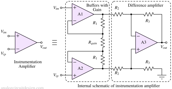
An instrumentation amplifier is built using a difference amplifier with two non-inverting opamps. The difference amplifier provides high differential gain while rejecting common mode signals. The non-inverting opamp also provides gain, but its main function is providing high input impedance, which cannot be provided by the difference amplifier alone.
Resistors R3 and R2 set the difference amplifier gain. Rgain and R1 set buffer stage gain. The gain can be set internally or externally through Rgain. If Rgain is inside the chip, high accuracy is possible because of the excellent matching properties of resistors.
Instrumentation amplifier derivation
We can analyze the instrumentation amplifier by separately analyzing common and differential mode excitation. The analysis is done in detail below:
Common mode excitation analysis

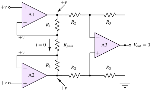
An instrumentation amplifier is not supposed to amplify common mode signals. The gain should be zero. To prove this, let's draw a simplified diagram of an instrumentation amplifier with common-mode signal "+v," as shown in Fig 2.
Due to virtual short, the inverting terminal of the opamps A1 and A2 are also (+v). This means that the current through the Rgain resistor is zero. Furthermore, the opamps A1 and A2 output will also be +v.
Now we see that the input of the difference amplifier made using A3 has both inputs equal to "+v." This is like the common mode excitation of a difference amplifier. From the lessons on difference amplifiers, we know that the common mode gain of difference amplifiers is zero. That concept also applies here. The output of A3 becomes zero if both inputs are excited with identical voltage.
Differential mode excitation analysis
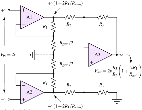
In differential mode excitation, if the positive terminal is provided with a "+v" voltage, the negative terminal is provided with a negative voltage "-v."
To simplify the analysis, we can split the Rgain resistor into two parts (Rgain / 2 each), as shown in Figure 3. This is possible because the two ends of the Rgain resistor experience differential voltage. The output of amplifier A1 now looks similar to the non-inverting amplifier configuration, where Rf = R1 and Rg = Rgain/2.

The output of the A1 amplifier (VA1) is :
$$V_{A1}=+v\left(1+2\cfrac{R_1}{R_{gain}/2}\right)$$
The output of the A2 amplifier (VA2) is :
$$V_{A2}=-v\left(1+2\cfrac{R_1}{R_{gain}/2}\right)$$
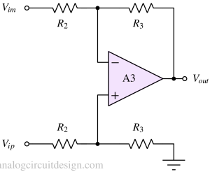
Input to the difference amplifier is VA1 and VA2. So, using the equation of difference amplifier :
$$V_{out}=\cfrac{R_3}{R_2}\left(V_{A2}-V_{A1}\right)$$
Substituting the values of VA1 and VA2 into the above equation:
$$V_{out}=\cfrac{R_3}{R_2}\left(1+\cfrac{2R_1}{R_{gain}}2v\right)$$
$$\cfrac{V_{out}}{2v}=\cfrac{R_3}{R_2}\left(1+\cfrac{2R_1}{R_{gain}}\right)$$
Effects of mismatch of resistors on instrumentation amplifiers
The mismatch of resistors can limit the CMRR of the overall instrumentation amplifier even if individual amplifiers have infinite CMRR. The mismatch directly impacts the common mode rejection, as the Difference amplifier article explains. The mismatch in the non-inverting stages in instrumentation amplifiers also impacts the common mode rejection.
Properties of instrumentation amplifier
- High AC and DC common mode rejection ratio.
- Low offset voltage and offset voltage drift
- High input impedance
- Low input bias and offset currents
- Precision gain setting
Instrumentation amplifier with Dynamic offset cancellation
The high gain usually amplifies the random/systematic offset with any amplifier. For example, the input offset is 1mV, and the gain is 500V/V. Then the output is already at 500mV. This offset is a trouble when the signal voltage is comparable, and we are concerned with absolute voltage reading.
So, it is desirable to have Voffset be very small (<10μV). This is done using dynamic offset cancellation techniques like autozeroing and chopping. If your target application is to amplify very small signals (in the range of 100μV), use instrumentation amplifiers with dynamic offset cancellation techniques.
Instrumentation vs. difference amplifier

A difference amplifier does not have a very high input resistance, while an instrumentation amplifier has a very high input resistance.
With a difference amplifier, it is possible to have a common mode voltage above the amplifier's supply voltage. This is not possible with an instrumentation amplifier.
Applications of instrumentation amplifiers
- Biomedical Instrumentation: In-amps are commonly used in medical devices for amplifying weak physiological signals such as ECG (electrocardiogram), EEG (electroencephalogram), EMG (electromyogram), and other bioelectric signals. Instrumentation amplifiers are very good at rejecting interference from common-mode noise sources.
- Strain Gauge Amplification: These are used to measure strain in structures, load cells, and force sensors. They amplify the small voltage changes produced by strain gauges.
- Temperature Measurement: In-amps are used in applications like thermocouples and RTD (resistance temperature detector) signal conditioning. They amplify the tiny voltage changes generated by temperature sensors, providing precise temperature readings.
- Bridge Amplification: In-amps are often used to amplify signals from Wheatstone bridge configurations. These bridges are used in strain gauges, load cells, and pressure transducers to measure changes in resistance, which are then converted into voltage signals.
- Industrial Automation: In manufacturing and process control applications, in-amps are used to amplify sensor signals from various sensors like thermocouples, pressure sensors, and load cells, helping to monitor and control industrial processes.
- Instrumentation and Test Equipment: In-amps are used in the design of high-precision instrumentation and test equipment, ensuring accurate and stable measurements. This includes spectrum analyzers, oscilloscopes, and other laboratory equipment.
- Audio Equipment: While not as common as in other applications, in-amps can be used in high-end audio equipment for signal conditioning to achieve low noise and high-fidelity amplification.