Analog Filters
An analog filter is a circuit that selectively allows certain frequencies to pass through while attenuating others. These filters are implemented using analog electronic components such as resistors, capacitors, inductors, transistors, and opamps. They are widely used in various applications, including audio processing, communications, and instrumentation.
Types of filters based on frequency shaping
The fundamental classification of filters is based on frequency shaping or frequency discrimination. Filters are supposed to treat different frequencies of the spectrum in different ways. Based upon this, filters can be classified as :
- Low pass filter
- High pass filter
- Bandpass filter
- Bandstop filter
Low pass filter
Low pass filters allow signals with less than the cut-off frequency to pass through them. Signals with frequencies higher than the cut-off frequency are attenuated—more about lowpass filters.
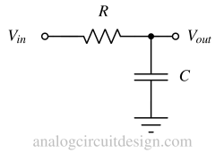
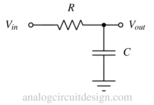
The simplest low pass filter is a passive RC low pass filter. It consists of a resistor (R) and a capacitor (C) connected in series. The output is taken from across the capacitor. At low frequencies, the capacitor's reactance (Xc = 1 / (2πfC)) is high; therefore, no current flows through the resistor. This means no voltage drop across the resistor and no attenuation of low-frequency signals. At high frequencies, the capacitor's reactance decreases, allowing more current to pass through the resistor, resulting in the attenuation of high-frequency signals.
Reactance is a concept similar to resistance that describes a component's opposition to the flow of alternating current (AC) due to its capacitance, inductance, or both. Reactance is measured in ohms and is represented by the symbol X.
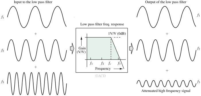
In the above figure, the signal with frequency f3 is attenuated, while the frequency f1 and f2 signals are passed as they are. This is because the frequency f3 lies beyond the low pass filter's cutoff frequency (fc). Signal frequencies f1 and f2 are within the cutoff frequency of the low pass filter.
High pass filter
High-pass filters allow signals higher than the cutoff frequency to pass through them. Conversely, signals lower than the cutoff frequency are attenuated—more about high-pass filters.
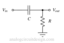
The simplest high pass filter is a passive RC high pass filter. It consists of a resistor (R) and a capacitor (C) connected in series. The output is taken from across the resistor. At low frequencies, the capacitor's reactance is high; therefore, no current flows through the resistor. This means no voltage drop across the resistor, and output equals zero (output is grounded). At high frequencies, the capacitor's reactance decreases, allowing more current to pass through the resistor, resulting in voltage formation across the resistor.
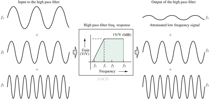
In the above figure, the signal with frequency f1 is attenuated, while the frequency f2 and f3 signals are passed as they are. This is because the frequency f1 lies below the high pass filter's cutoff frequency (fc). Signal frequencies f2 and f3 are higher than the cutoff frequency of the high pass filter.
Bandpass filter
Bandpass filters allow signals that pass frequencies within a specific range (called passband) and attenuate frequencies outside that range—more about bandpass filters. The region between frequency fL and fH is called the passband region because any signal frequency in this region is allowed to pass without attenuation. Outside this region, the signal is attenuated. fL is the lower cutoff frequency, and fH is the higher cutoff frequency.

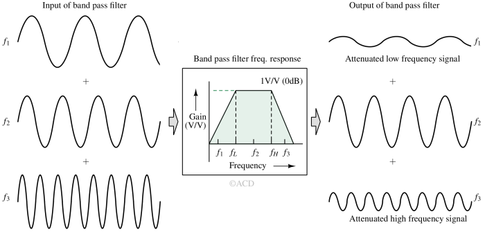 In the above figure, the bandpass filter allows only signal frequency f2. It attenuates the signals with frequencies f1 and f3. Signal frequency f2 is allowed because it lies in between fL and fH. The other two signal frequencies are attenuated because they are outside the passband region.
Bandstop filter
A band-stop or notch filter is an analog or digital filter that attenuates or rejects a specific range of frequencies while allowing all other frequencies to pass through. The following figure shows the gain vs. frequency response of a bandstop filter. Frequencies lesser than fL and frequencies higher than fH are not attenuated. Frequencies between fL and fH are attenuated. 
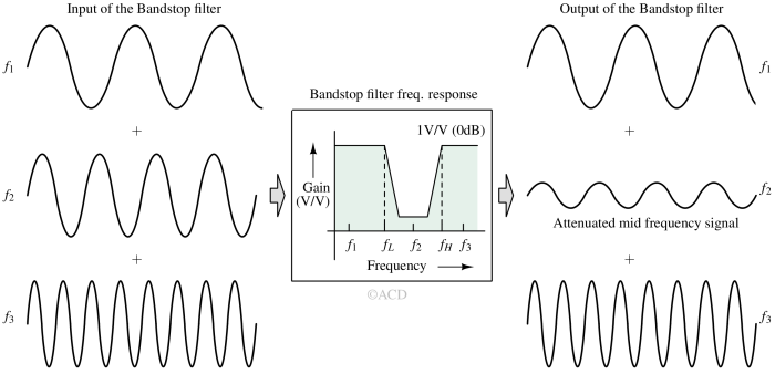
The above example in Figure 4 shows that the bandstop filter attenuates the signal with frequency f2. The signals with frequencies f1 and f2 are not attenuated because these are present outside the bandstop range. The bandstop range is between fL and fH.
If the gap between fL and fH becomes very narrow, it is better termed as a notch filter. The width of this notch and its depth (level of attenuation) can be adjusted by tuning the filter's parameters such as center frequency, bandwidth, and Q-factor.
Types of filters based on active or passive components
Active and passive filters are two broad categories used in electronics, each with its own characteristics, advantages, and applications. Active filters incorporate active components such as transistors and operational amplifiers (op-amps) along with passive components like resistors, inductors, and capacitors. Passive filters, on the other hand, consist of only passive components.
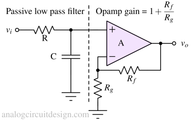
Active filters
- Filters using active elements like transistors and opamps are generally called active filters.
- Active filters can provide amplification in the passband region.
- It can simplify filter design.
- Power consumption is more because of the active components.
- It is more noisy because of additional active components.
- Very high Q can be achieved without the use of physical inductors.
- Input impedance can be made very high by leveraging the high input impedance of transistor/op-amp.
Passive filters
- Filters made using only resistors, capacitors, and inductors are passive filters.
- These filters cannot provide amplification in the passband region.
- Complex function filters (e.g., Chebyshev, Bessel, etc) are difficult to design.
- Power consumption is lower.
- Relatively less noisy because of the absence of active components.
- Input impedance is dependent on the passive component value.
- The quality factor cannot be increased beyond 0.707.
Key terminologies of analog filters
Some of the very common terminologies used for classifying analog filters are :
Order of filters
The order of a filter indicates the minimum number of reactive components that the filter will require. The definition of "order" comes from the differential equation governing the filter's behavior.
Frequency response plot
It is a graph of gain magnitude (V/V or dB) and phase (o) of transfer function versus frequency. Frequency response is important to check how a circuit behaves for different input frequencies.
$$\text{Gain}=\cfrac{V_{out}}{V_{in}}$$
-3dB frequency (f-3dB)
In a low-pass filter, the cutoff frequency is the highest frequency below which filter allows the signal to pass. Input frequencies higher than the cutoff frequency are attenuated.
Practically, the attenuation of higher frequency does not happen abruptly. So, as a definition, the cut-off frequency is defined when the output power of the filter becomes half of the input power (keeping load resistance at the input and output the same).
$$\cfrac{V_o^2}{R}=\cfrac{V_i^2}{2R}$$
For a first order low pass filter, the transfer function is :
$$\left|\cfrac{V_o}{V_i}\right|=\cfrac{1}{\sqrt{1+\left(\cfrac{f}{f_{3dB}}\right)^2}}$$
Center frequency (fo)
In a bandpass filter, it is the frequency where the gain is maximum. For an LC based bandpass filter,
$$f_c=\cfrac{1}{2\pi{}\sqrt{LC}}$$
Bandwidth (BW)
Bandwidth is the range of frequency in which the input signal is allowed to pass without attenuation. For a low pass filter, the bandwidth is f3dB (0-f3dB). For a bandpass filter, bandwidth is fbw\=|fH-fL|. The bandwidth of the high pass filter and notch filter is not defined.
Quality factor (Q)
The quality factor (Q) is defined for a bandpass or notch filter. It signifies how sharp the passband or stopband of the filter is. A sharper passband or stopband means more selectivity. It can attenuate a very narrow range of frequencies without affecting other frequencies. The Q also shows how long the energy is stored in the filter network once supplied. Usually, every LC circuit has parasitic R. This R dissipates the energy stored in the energy storage reactive elements (inductor L and capacitor C). The lesser the energy dissipation, the longer the energy stored in the circuit and the higher the quality factor.
$$Q=2\pi{}\times{}\cfrac{\text{energy stored}}{\text{energy dissipated per cycle}}$$
Practical way to determine the quality factor :
We observe oscillations when a LC based bandpass filter is excited with a step response. Longer the oscillations last, higher is the quality factor. The number of peaks above 1% of initial amplitude is approximately equal to the quality factor.
Damping factor
It denotes how faster the oscillations will die in a filter. The higher the damping factor, the faster the oscillations will die. It means the oscillations will have less number of peaks in the time domain. It is inversely proportional to the Quality factor (Q).
The damping factor determines whether the filter will have a Butterworth, Chebyshev, or Bessel's response. Butterworth filter has a maximally flat response, which is the most commonly used filter.
Roll-off rate
Roll-off rate is the rate of change of the filter's gain versus frequency. For first-order filters (low pass or high pass), roll-off rate is 20dB/dec.
20dB/dec means the filter gain will change by 20dB (10x) for a decade (10x) change in frequency.
Applications of filters
Some very common applications of analog filters are :
RF
In Radio-frequencies, filters allow us to choose the desired signal out of the sea of undesirable signals. The signal of interest should be present in a unique frequency band.
Audio electronics
One of the key application is to build audio equalisers where it let us attenuate some frequencies and boost others.
AC/DC-DC converters
In switching AC-DC or DC-DC regulators, filters are used to suppress the high-frequency switching noise.
Data converters
In analog-to-digital converters, filters are used to avoid aliasing. In digital-to-analog converters, the filters suppress the higher-order harmonics (smoothening filters).