Operational Amplifiers (Op Amp)
Op Amp is a short name for operational amplifiers. It amplifies the difference between two input terminals and forces the output terminal to reflect the amplified voltage. It is called "operational" because it can be used for addition, subtraction, integration, differentiation, logarithms, gain, buffer (to amplify power), etc. It is the most versatile integrated circuit in electronics.
Operational Amplifier Symbol

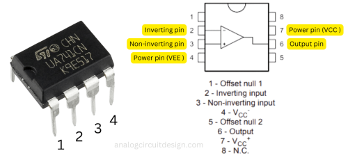
Most common op-amps have two input terminals (inverting and non-inverting terminal), one output terminal and two power terminals. Power terminals are VCC and VEE. The simplest form of relationship between the input and output is:
$$V_{out}=A(V_{ip}-V_{im})$$
Op-amps are a fundamental building block in analog electronic design, and their versatility and predictable behavior make them essential in applications ranging from audio amplification to instrumentation and control systems.
Golden Rules of an ideal opamp
For an op-amp configured in negative feedback mode, following rules help us analyze opamp circuits :
Opamp Golden Rules
- Op Amp tries to keep both the inputs voltage same (virtual short)
- No current flow into the input terminals.
Ideal opamp properties
An ideal op-amp is a perfect device used for simplified analysis, while a real op-amp has practical limitations like finite gain, bandwidth, and nonzero offset, which affect real-world circuit performance.
| Property | Ideal Opamp | Meaning | Real Opamp |
|---|---|---|---|
| Open-loop gain (A) | Infinte | Vip = Vim for finite output | 100-100,000 (decreases with frequency) |
| Input offset voltage | Zero | No output error when inputs are equal | 10uV - 10mV |
| Input impedance | Infinite | No current enters input terminals | 100kΩ-1GΩ (decreases with frequency) |
| Output impedance | Zero | Ideal voltage source output | < 1Ω |
| Bandwidth | Infinite | No frequency dependence | 10kHz-10GHz |
| CMRR | Infinite | Rejects common-mode ((Vip+Vim)/2) signals completely | ~100dB (decreases with frequency) |
| Slew-rate | Infinite | Instantaneous response | 0.01-10,000 V/µs |
| Noise | Zero | Infinitely high sensitivity | 0.5nV/rtHz to 10nV/rtHz |
| PSRR | Infinite | Supply voltage fluctuations do not affect output voltage | ~100dB (decreases with frequency) |
Learn more about real opamp properties - Real operational amplifier properties.
Mode of operation of an opamp
An opamp can be configured in two ways:
Closed loop or Negative Feedback mode
The most widely used operational amplifier setup is the closed-loop configuration. In this arrangement, output of the opamp is connected to its inverting input via some network. The Golden rules apply here. The gain decreases significantly but becomes highly accurate and stable with respect to temperature.

Open loop and positive feedback mode
In a comparator mode, the opamp compares the two input voltages and produce "high" or "low" output based on the comparison. This mode is commonly referred to as open-loop operation. For noise immunity and speed, positive-feedback is also used, creating a Schmitt-trigger. The Golden rules do not apply.

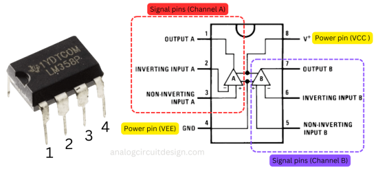
Pinouts of opamps
Model of a real operational amplifier

A simple model can be constructed for an opamp as shown above. Both the inputs see Zin as input impedance. The output is determined by a voltage-controlled voltage source (VCVS). The output of the VCVS is determined by the difference of Vip and Vim. Also, it offers a gain of A. An output impedance Zout is added in the series of the VCVS.
Common Operational Amplifier Configurations
Op-amps can be used in a variety of configurations, such as inverting, non-inverting, voltage followers, integrators, differentiators, and more. All the following configurations are closed loop (negative feedback configuration).
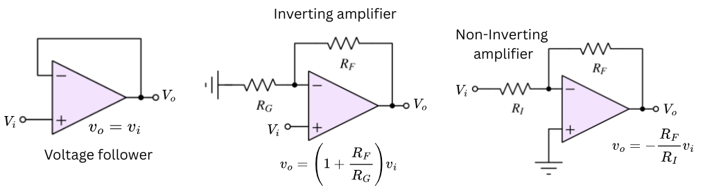
- Voltage follower (or Buffer) : The output voltage follows the input voltage. Therefore, output voltage is in-phase with the input voltage. This configuration is used to isolate load and impedance matching. $$V_{o}=V_{i}$$
- Inverting amplifier : The output of an inverting amplifier is 180° out-of-phase of that of the input. The input can be gained up by a factor of \(R_F/R_I\). The input-output relationship is : $$V_{o}=-\cfrac{R_F}{R_I}V_{i}$$
- Non-inverting amplifier : The output of a non-inverting amplifier is in-phase (0°) with the input of the amplifier. The input can be gained up by a factor of (\(1+R_F/R_G\)). The input-output relationship is: $$V_{out}=-\left(1+\cfrac{R_F}{R_G}\right)V_{in}$$
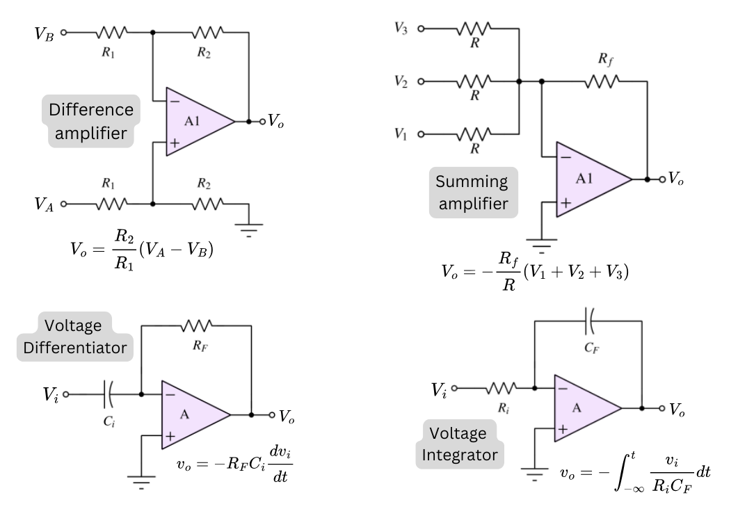
- Difference amplifier : This configuration amplifies the voltage difference between two input signals while rejecting any voltage common to both. It is commonly used for noise reduction and as the core of instrumentation amplifiers. The input-output relationship is: $$V_o=\cfrac{R_2}{R_1}\left(V_A-V_B\right)$$
- Summing amplifier : This configuration outputs the weighted sum of multiple input voltages. It is commonly used in audio mixing and signal processing to combine several signals into one. The input and output relationship is : $$V_o=-\cfrac{R_f}{R}\left(V_1+V_2+V_3\right)$$
- Voltage differentiator : This topology produces an output proportional to the rate of change (derivative) of the input voltage. It is used in waveform shaping, change detection, edge detection etc. The input-output relationship is : $$V_o=-R_FC_i\cfrac{dv_i}{dt}$$
- Voltage integrator : This topology produces an output proportional to the time integral of the input voltage. It is used in applications such as signal integration, waveform transformation, and analog computation. The input-output relationship is : $$V_o=-\int_{-\infty}^{t}\cfrac{v_i}{R_iC_F}dt$$
Active filters
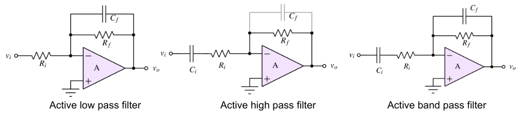
Operational amplifiers are used to make active filters. Unlike passive filters, active filters have following advantages:
- Can amplify signals
- Offers low output impedance (reducing loading effects)
- Can offers high input impedance
- Provides higher quality factor
- Sharper roll-off
Common types include low-pass, high-pass, band-pass, band-stop, and all-pass filters.
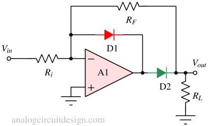
Precision rectifiers
Operational amplifier can be used to overcome the voltage drop limitation of ordinary diodes. In a standard diode rectifier, the forward voltage drop (~0.7 V for silicon) causes inaccuracy when dealing with small signals. By incorporating an op-amp with a diode in its feedback loop, the effective threshold voltage becomes nearly zero, allowing accurate rectification of very low-level AC signals.
More about precision rectifiers : Precision rectifier circuits using op-amps
Operational amplifier classifications
In real life, opamps have lot of non-idealities. To achieve some parameters better, some other parameters are traded-off. For example, to achieve the best speed to power ratio, input bias current is allowed by using BJT based opamps.
Classification based on Technology:
- Bipolar Junction Transistor (BJT) Op-Amps: These op-amps use bipolar junction transistors as their active elements. They are known for their high-bandwidth to quiescent current ratio, low offset voltage, and good linearity with manageable input impedance. These are able to provide high currents at the load. The input bias current is non-zero.
- Junction Field-Effect Transistor (FET) Op-Amps: FET-based op-amps use field-effect transistors as the amplifying devices. They are known for their high input impedance and low input bias currents. They offer higher bandwidth than CMOS opamps for the same Quiescent current. However, in comparison to BJT opamps, these take more Quiescent current and are costlier. The input bias current is zero.
- CMOS Op-Amps: Complementary Metal-Oxide-Semiconductor (CMOS) op-amps use CMOS technology, making them suitable for low-power applications. They typically have very high input impedance and bandwidth (because of transistor scaling). However, the load current capability is lower in CMOS opamps than in BJT opamps for the same power consumption. The input bias current is zero.
Classification based on Functionality:
- General-Purpose Op-Amps: These are versatile op-amps designed for a wide range of applications. Examples include the LM741 and LM324.
- Precision Op-Amps: Precision op-amps are characterized by low offset voltage, low offset voltage across temperature drift, and high common-mode rejection ratio (CMRR). They are used in applications where accuracy and stability are critical. Types of precision op-amps:
- High-Speed Op-Amps: These op-amps are designed for high-frequency applications, such as in video amplifiers and RF circuits. They have fast response times and wide bandwidths.
- Low-Noise Op-Amps: Low-noise op-amps are designed to minimize electrical noise and are commonly used in audio and sensor applications:
- Rail-to-Rail Op-Amps: These op-amps are designed to operate with input and output voltages that can approach the power supply rail voltages, making them suitable for single-supply applications. E.g., ADA4807
- Current Feedback Op-Amps: These op-amps use a current feedback architecture instead of voltage feedback, which can provide high bandwidth and fast transient response at the expense of precision and current-noise. E.g., OPA695