Schmitt trigger
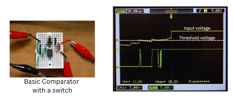
A Schmitt Trigger is a comparator circuit with hysteresis, meaning it has two different threshold voltages for rising and falling input signals. This prevents false triggering from noise or slow signal transitions. It uses positive feedback to shift the threshold dynamically based on the output state. Commonly built using op-amps or comparators, Schmitt Triggers are used in signal conditioning, switch debouncing, and converting analog signals to clean digital outputs.
Types of Schmitt Trigger
There are two main types of Schmitt Triggers: Inverting and Non-Inverting. In a Non-Inverting Schmitt Trigger, the input is on the non-inverting terminal, and the output follows the input.
Inverting Schmitt Trigger
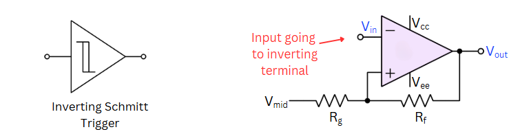
In an Inverting Schmitt Trigger, the input is applied to the inverting terminal, and the output is opposite to the input.
Non-inverting Schmitt Trigger
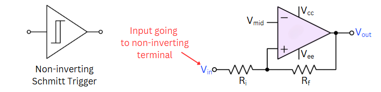 In a Non-Inverting Schmitt Trigger, the input is on the non-inverting terminal, and the output follows the input.
Properties of a Schmitt trigger
Important properties of Schmitt Trigger are mentioned below :
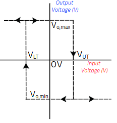
Thresholds

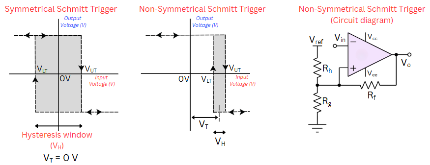
A typical Schmitt trigger has two thresholds defined by Output Voltage state and Resistor Divider formed by Rf and Rg.
$$V_T=V_{out}\cfrac{R_g}{R_g+R_f}$$
When the output is saturated to VCC (or Vo,max) the threshold voltage is called upper threshold voltage. It is called upper threshold voltage because the value of this threshold is higher (VUT).
$$V_{UT}=V_{o,max}\cfrac{R_g}{R_g+R_f}$$
When the output is saturated to VEE (or Vo,min) the threshold voltage is called lower threshold voltage (VLT).
$$V_{LT}=V_{o,min}\cfrac{R_g}{R_g+R_f}$$
Hysteresis
Hysteresis in a Schmitt Trigger refers gap between the two different threshold voltages—one for rising input and another for falling input. This gap prevents false triggering from noise or slow signals, ensuring clean and stable output transitions.
$$V_H=V_{UT}-V_{LT}$$
Working of Schmitt trigger
Schmitt Trigger is a positive feedback circuit. Due to this, output will always saturate to either Vo,max or Vo,min. We will use an Inverting Schmitt trigger as an example. The output is originally saturated at Vo,max. So, the current threshold is VUT which is called upper threshold. When the input crosses the upper threshold, the output toggles from high to low and saturates at Vo,min. With that, the threshold changes to lower threshold, VLT. If the input later returns above the original threshold, the output remains unchanged. If the input goes below the lower threshold, the output reverts back to Vo,max which is its original voltage. Non-inverting Schmitt trigger will have opposite input to output relationship.
Following video provides a nice graphical explanation of Schmitt Trigger :
Applications of Schmitt trigger
- Noise Immunity: Schmitt triggers are effective in eliminating noise and signal distortions in digital circuits, ensuring cleaner transitions between logic states by providing noise immunity.
- Signal Conditioning: They're used to condition analog signals into digital signals or square waveforms, making them useful in signal processing and sensor applications.
- Debouncing: In digital systems, Schmitt triggers help in debouncing switches or mechanical contacts, ensuring that only clean and stable signals are considered.
Different circuit construction of Schmitt trigger
Opamp or comparator based Schmitt trigger
Steps to convert an opamp / comparator into a Schmitt trigger:
- Connect the non-inverting input (+) of the op-amp to output using R2.
- Also, connect R1 from the non-inverting pin to a reference voltage (Vref, could be connected to mid-supply as well).
- Connect the inverting input (-) of the op-amp to the input voltage.
- Optionally, we can add capacitors or diodes for filtering or clamping if needed.

Transistor based Schmitt-trigger
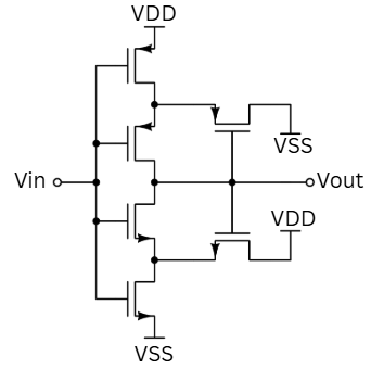
The above circuit is an optimised Schmitt trigger commonly used in integrated circuit designs. This was designed by Filanovsky and Baltes.
Off-the-shelf IC Schmitt trigger
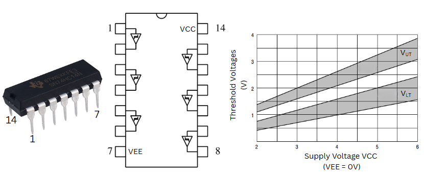
Integrated circuit-based Schmitt triggers are available in various IC packages, providing a convenient solution for implementing Schmitt triggers in circuits.
Non-Symmetrical Schmitt Trigger
Conclusion
Schmitt triggers are essential components in electronics, particularly in digital systems and signal conditioning circuits, due to their ability to provide noise immunity, stabilize input signals, and convert non-linear input signals into clean digital outputs with well-defined transitions. They are versatile and find applications in various fields of electronics, such as communication, automation, and signal processing.