L293 motor driver IC
A motor driver IC, plays a crucial intermediary between the microcontroller (such as Arduino) and the motors it directs. Given that motors often demand higher current and power than the microcontroller's pins can typically deliver, a specialized control chip, known as a motor driver, becomes essential for this purpose.
Among the widely employed motor driver ICs are those belonging to the L293 series, such as L293D and L293NE. These ICs are specifically engineered to manage two DC motors concurrently. The L293D, for instance, comprises of two H-bridges (also called dual-H bridge), a fundamental circuit for governing low-current-rated motors. In this context, we'll specifically refer to the motor driver IC as L293D, which boasts a total of 16 pins.
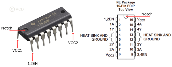
Pin diagram and description of L293 IC

| PIN | Input/Output/Power | Description | |
|---|---|---|---|
| Name | Number | ||
| 1,2EN | 1 | Input | When this is HIGH the left part (Channel 1 & 2) of the IC will work and when it is LOW the left part won’t work. |
| 1A,2A,3A,4A | 2,7,10,15 | Input | When this pin is HIGH the current will flow though output. E.g., if 1A is HIGH, 1Y will also be HIGH. These are connected to microcontroller |
| 1Y,2Y,3Y,4Y | 3,6,11,14 | Output | These are connected to motor. These are the output pins which will drive high currents. |
| 3,4EN | 9 | Input | When this is HIGH the right part (Channel 3 & 4) of the IC will work and when it is LOW the right part won’t work. |
| GROUND | 4,5,12,13 | Reference | Device ground and heat sink pin. Connect to printed-circuit-board ground plane with multiple solid vias. |
| VCC1 | 16 | Power | 5-V supply for internal logic translation |
| VCC2 | 8 | Power | High current capable power supply for outputs (4.5 V to 36 V). |
The L293D is a 16 pin IC, with eight pins, on each side, dedicated to the controlling of a motor. There are 2 INPUT pins, 2 OUTPUT pins and 1 ENABLE pin for each motor. L293D consist of two H-bridge. H-bridge is the simplest circuit for controlling a low current rated motor.
How to use L293 motor driver IC?
We need following materials to use L293 IC -
- Integrated Circuit L293D.
- Four 1-micro-farad capacitors
- 12V power source for motor and 5V power source for micro-controller.
- Two DC motors
- Micro-controller (e.g., Arduino)
- Miscellaneous items such as soldering iron, soldering wire, perf-board, wires, male/female header pins etc.
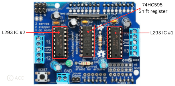
Arduino motor driver shield based on L293 IC

The system involves two connections for 5V 'hobby' servos linked to the Arduino's high-resolution timer. Utilizing the L293D chipset with four H-Bridges, it delivers 0.6A per bridge (peaking at 1.2A) and features safety measures like thermal shutdown protection and internal kickback protection diodes. It operates motors between 4.5VDC to 25VDC, supporting up to four bi-directional DC motors, each with independent 8-bit speed control (about 0.5% resolution). Additionally, it accommodates two stepper motors—unipolar or bipolar—capable of single coil, double coil, or interleaved stepping modes.
Frequently Asked Questions
Following are some frequently asked questions related to L293 motor driver IC:
What is the difference between L293 and L298 IC?
The L293D functions as a quadruple motor driver, featuring separate input-output lines utilizing a half-H driver setup. In comparison, the L298N serves as a dual full-H driver, necessitating a complete full-H driver configuration and cannot operate independently in a half-H driver mode.
What is the reason behind having 4 ground pins in the IC?
The motor driver IC manages substantial currents, leading to increased heat generation within the chip. To address this issue, a heat sink becomes necessary for heat dissipation. The presence of 4 ground pins serves a specific purpose in this con\text. When these pins are soldered onto a printed circuit board (PCB), they create a significant metallic area between the ground connections. This enlarged metallic area facilitates efficient heat dissipation, aiding in the reduction of the IC's temperature.
Why are capacitors necessary in this setup?
DC motors, being inductive loads, generate back electromotive force (EMF) when powered by a voltage source. In motor operations, voltage fluctuations may occur, especially during sudden changes in direction, such as an abrupt reversal while the motor is already in motion. These voltage fluctuations can be substantial and potentially harmful to the IC. To mitigate this risk, the inclusion of four capacitors serves a crucial role. They aid in smoothing out and stabilizing the significant variations in current, thus safeguarding the IC from potential damage caused by abrupt voltage fluctuations.
How to control speed of DC motor?
The most common method for regulating a DC motor's speed is pulse width modulation (PWM). This technique provides pulses of varying width to control the average voltage applied to the motor. It's highly efficient, minimizing power loss without necessitating complex control circuits.
PWM is accomplished by adjusting the pulses sent to the motor driver IC's enable pin using a microcontroller, thereby controlling the voltage applied to the motor.