LC Oscillators
An LC resonator (tank or tuned circuit) is a parallel or series combination of an inductor and a capacitor. It is the most fundamental building block of oscillators and it is very popular. In ideal conditions (no resistance in the circuit), when the inductor or the capacitor are energized and connected together, sustained voltage and current oscillations are observed. In reality, without any active component doing the energy compensation, the oscillations die.
Basic LC oscillator tank circuit
A parallel connection of an inductor and capacitor is usually termed an LC tank circuit.
Suppose the capacitor is charged to voltage Vp and connected across the inductor. In that case, the capacitor's electric field energy is converted into the inductor's magnetic field energy. After some time, the magnetic field energy of the inductor will convert to electric field energy. This back-and-forth exchange of energy is called resonance.
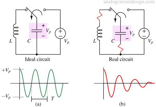
When the capacitor is first charged to Vp and connected across the inductor, the current will start from zero (Lenz law in inductor). Because of the growing current, the capacitor will lose charge (and voltage will drop). When the voltage across the capacitor drops to zero, it loses all its energy. This is when the energy inside the inductor is at its peak, and the current in the circuit also peaks. From now the capacitor starts charging from reverse and gradually reaches -Vp voltage. At this point, the current in the circuit will become zero because the inductor has lost all its energy and transferred it to the capacitor. From this point, it is analogous to a capacitor charged with -Vp.
Resonance frequency or center frequency
To intuitively derive the resonant frequency of a LC tank circuit, we should note that the voltage across the inductor and capacitor is the same. Also, the current through the inductor and capacitor is the same. So, the impedance is matching during resonance.
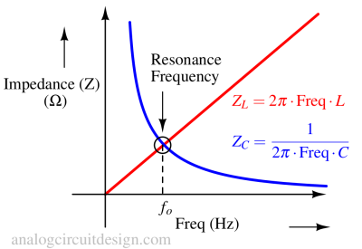
$$Z_L = Z_C$$
$$2\pi{}\cdot{}f_o\cdot{}L=\cfrac{1}{2\pi{}\cdot{}f_o\cdot{}C}$$
$$\implies{}f_o=\cfrac{1}{2\pi{}\sqrt{LC}}$$
Damped oscillations
In a lossless LC oscillator, there is no damping, and the initial energy decides the amplitude of the oscillation.
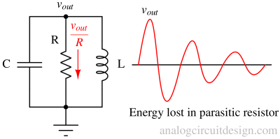
Practically, some dissipating force (represented by a resistor) damps out the oscillations, as shown in Fig 2. The oscillations die out after several cycles depending on the Q factor. The Q factor is inversely proportional to the damping factor.
Due to voltage drop across the series parasitic resistance or current stealing from parallel parasitic resistance, the impedance does not match for damped oscillations.
Quality factor of oscillator (Q)
Usually, the quality factor is defined for the harmonic oscillator. The Q factor is the ratio of the magnitude of storage energy to dissipative energy. So, if dissipative energy is high, Q-factor is low, and oscillations will die faster.
$$Q = \omega{}\times{}\cfrac{\text{Maximum stored energy}}{\text{energy lost in one cycle}}$$
An oscillator where the oscillations do not die down has an infinite Q-factor. Our intent with any harmonic oscillator design is to make the Q-factor infinite. A passive LC oscillator will have a finite Q-factor because of parasitic resistance. This resistance will dissipate energy from the tank, and the oscillations will die. An active element is used (with positive feedback) to replenish the exact amount of energy so that oscillations sustain forever.
Active LC oscillator circuit
In reality, the LC tank circuit is always lossy. The energy is lost as heat through the parasitic resistance as shown in Fig 2. The loss of energy is visible through the amplitude of oscillation. Gradually, the amplitude reduces, so the energy stored in the tank is reduced.
If we can monitor the amplitude and inject energy equal to the energy lost, then the amplitude can be sustained. Monitoring and supplying the energy requires an active element which can be any transistor like BJT and MOSFET.
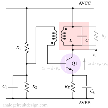
In Fig 4, transistor Q1 is the active component. The transistor is setup as a common emitter gain stage.
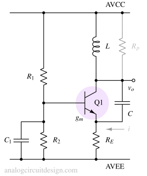
Cross coupled LC oscillator
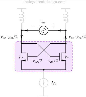
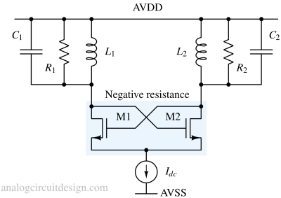
A cross-coupled LC oscillator, also known as an LC tank oscillator, is a type of electronic oscillator circuit used to generate continuous sinusoidal waveforms at radio frequencies (RF) or microwave frequencies. It's called "cross-coupled" because it utilizes two active devices (typically transistors) that are connected in a feedback loop and interact with each other to sustain oscillations.
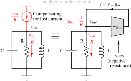
In the above figure, we are trying to compensate for the lost energy using additional current Vout/R. In a normal resistor, the current goes into the resistor if a voltage is applied. However, if the voltage is applied, the current comes out. So, the current direction is reversed in comparison to a normal resistor. Therefore, it is also called a negative resistor. Shown in the \right side of the Figure, the negative resistor is made using a voltage-controlled current source (VCCS), which senses the Vout voltage and sends a current that is equal to the current lost in resistor R. Current lost in resistor R is Vout/R.
Now, how do we find the exact value of gm? Voutgm is the current supplied by the negative resistance (VCCS), which should equal Vout/R. So,
$$g_m=\cfrac{1}{R}$$
In actual circuits, finding R is not possible due to manufacturing variations. So, feedback is necessary to account for the variations in R. Also, R is never added intentionally. It is the stray resistance in the circuit which causes finite resistance.
