Low pass filters
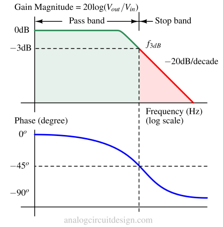
A low-pass filter is a circuit that allows low-frequency signals to pass through (sometimes, it also offers gain) and attenuates high-frequency signals beyond the cut-off frequency. The cutoff frequency is the point at which the filter attenuates the signal significantly.
In audio systems, low-pass filters are used in speaker crossovers to direct low-frequency signals to woofers, which handle bass and midrange frequencies. These are used to remove high-frequency components from the input signal before sampling. This prevents aliasing, where high-frequency signals fold back into the desired frequency range, causing distortion.
Lowpass filter transfer function
The general mathematical transfer function of a low-pass filter is :
$$\cfrac{v_o(s)}{v_i(s)}=\cfrac{1}{1+\cfrac{s}{\omega{}_oQ}+\cfrac{s^2}{\omega{}_o^2}}$$
Passive low pass filter
A passive low-pass filter uses passive components, such as resistors, capacitors, and inductors, to achieve the low-pass frequency response. It does not require an external power source or active components like operational amplifiers, BJTs, and MOSFETs as a gain block. Passive filters are economical, power efficient, and simple to design. Passive filter gain is always less than or equal to unity. Also, the roll-off rate may not be as good as an active low-pass filter.
First order passive low pass filters
First-order low-pass filters are the simplest implementation of low-pass filters. It consists of a single R-C or R-L to implement the filter. It is called "first-order" because its frequency response has a slope of -20 dB per decade.
RC low pass filter
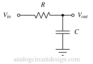
The most common implementation of a first-order low-pass filter is the RC filter configuration. It consists of a resistor (R) and a capacitor (C) connected in series. The output is taken across the capacitor.
The frequency response of a first-order RC low-pass filter is given by the transfer function:
$$H(s)=\cfrac{1}{1+sRC}$$
RL low pass filter
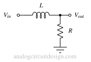
The RL filter configuration is the less common implementation of a first-order low-pass filter. It is because inductors are quite bulky. It consists of an inductor (L) and a resistor (R) connected in series. The output is taken across the resistor.
The frequency response of a first-order RL low-pass filter is given by the transfer function:
$$H(s)=\cfrac{1}{1+sL/R}$$
Second order passive low pass filters
Second-order filters provide a higher roll-off rate than first-order filters. However, extra passive components are required to construct higher-order filters. The roll-off rate of second-order filters is -40dB/dec. While for the first order filter is only -20dB/dec.
A roll-off rate of -40dB/dec means that with a 10 times increase in frequency, the signal will be attenuated by 100 times. A higher roll-off rate means more suppression of frequency beyond the cut-off frequency of the low pass filter.
RC-RC low pass filter
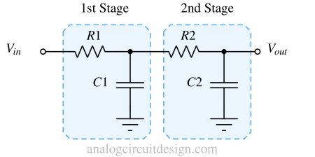
As shown in above figure, the first stage provides an attenuation of 20dB/decade in the stop band. After the addition of the second stage, the combined filter provides an attenuation of 40dB/decade in the stop band. The more stages are added, the attenuation becomes steeper. At low frequency (pass-band of the low-pass filter), the capacitor is acting open. So, no current and hence no voltage drop across R1 and R2.
With R1=R2=R and C1=C2=C the quality factor Q becomes 1/3. Q approaches the maximum value of 1/2 if the impedance of the second RC stage is made much larger than the first. Most filters require Q larger than 1/2.
The transfer function of the RC-RC low pass filter is mentioned below : $$\cfrac{V_{out}}{V_{in}}=\cfrac{1}{s^2R^2C^2+3sRC+1}$$
$$Q=\cfrac{1}{3}$$
$$\omega{}_o=\cfrac{1}{RC}$$
RLC low pass filter
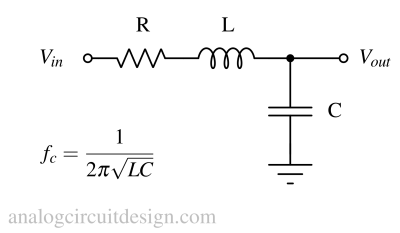
A second-order low-pass filter can also be made using RLC. The cutoff frequency is ω = 1/√LC, after this the inductor becomes open and the capacitor becomes almost short to ground making Vout approaching zero in stopband. In pass-band (low frequency), the inductor acts as short and capacitor acts as open which allows the signal to flow from Vin to Vout. The transfer function of the RLC low pass filter shown above is mentioned below:

Active low pass filter
An active filter low-pass filter includes active components such as an amplifier or transistor. Active low-pass filters can provide gain in the pass band. These filters derive the energy (to provide gain) from the supply voltage.
The cutoff frequency of the low pass filter (f3dB) should always be less than the opamp's gain-bandwidth product (GBW). Otherwise, the low pass filter's cutoff frequency would be GBW instead of f3dB.
First order active filters
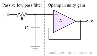
The passive low pass filter is cascaded with an opamp in unity gain to make an active low pass filter as shown above. The opamp isolates it from the load applied at the Vout node. However, the gain is fixed at +1V/V. So, to obtain gain, a non-inverting amplifier with gain can be used in cascade.
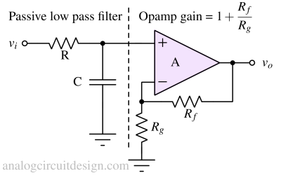
In the above figure, the non-inverting amplifier provides a gain of 1+Rf/Rg. So, the pass band has gain as well and the filter response won't change because there won't be any loading effect.
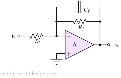
A low pass filter can be created using inverting amplifier topology also where the gain is -Rf/Ri in the pass band.
At low frequencies, the Cf is an open circuit. So, all the current flows through the Rf resistor. Hence gain is -Rf/Ri. At higher frequencies, Cf's impedance will reduce and will become lesser than Rf. So the gain is decided by Cf instead. Therefore gain at higher frequency is 1/ωCfRi. This shows that with frequency, the gain will drop and form a stop band.
Second order active filters
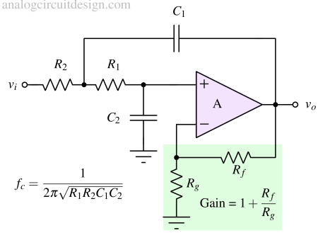
Second-order active low-pass filters provide second-order (or two-pole) filtering characteristics. These are designed using active components like operational amplifiers (op-amps) to achieve specific frequency response characteristics. These filters can provide steeper roll-off rates compared to first-order filters.
- Frequency Response: Second-order active filters exhibit a roll-off rate of -40 dB/decade (or -12 dB/octave) beyond the cutoff frequency (in the stop band).
- Q Factor (Quality Factor): For a second-order active low-pass filter, the Q factor determines how abrupt the transition between passband and stopband is. Lower the Q factor, the attenuation starts from a frequency lesser than the cut-off frequency which may be undesirable.
- Amplification: Second-order active filters can provide signal amplification or attenuation depending on the design and component values used. The amplification can be useful in applications where signal gain or loss is necessary.
- Frequency Tunability: Many second-order active filters are tunable, meaning you can adjust the cutoff frequency or center frequency by changing the values of the components within the filter circuit.
Transient response

Step response through a low pass filter.
Treble cut filters
A treble-cut filter is a low-pass filter that attenuates or reduces higher frequencies in an audio signal while allowing lower frequencies to pass through unaffected.
-
Tone Shaping: It allows users to adjust the tonal characteristics of an audio signal by attenuating high frequencies. This can soften or round off the sound, reducing sharpness or brightness in the output.
-
Noise Reduction: Cutting high frequencies can help to reduce unwanted noise, such as hiss or interference, which often occurs in the higher frequency range.
-
Speaker Protection: In some cases, excessive high-frequency content can potentially damage speakers. A treble-cut filter can prevent such damage by limiting these frequencies.
Treble-cut filters can be implemented in various audio devices, including audio mixers, equalizers, guitar amplifiers, and audio effects units. They typically utilize capacitors, resistors, and sometimes inductors to achieve the desired frequency response.