Nodal analysis
Nodal analysis formulates an equation at each electrical node, mandating that the total incoming branch currents at a node must equate to zero. It is the application of KCL. It expresses the branch currents in terms of circuit node voltage and impedance.
Most SPICE programs use nodal analysis to compute the DC operating point. This is because having a finite number of nodes makes analysis more systematic.
Reference node and why is it important?
The voltage at any node is the voltage difference between that node and a reference node. Usually, the node tied to ground (0) is usually called a Reference node. However, if there is no mention of a reference node, we can assume any node tied to ground (0) and use nodal analysis.
The procedure of nodal analysis
- Identify all the nodes in the circuit.
- Select one node as the ground (zero) reference. The other voltages will be with reference to the selected ground reference node.
- Assign an unknown variable (voltage) to each node. Find all the currents entering the node. If there is an outgoing current, represent it using a negative sign. Again, this is a matter of convention to represent incoming currents using positive signs and outgoing currents using negative signs.
- For each node, form a KCL equation.
- If voltage sources exist between two unknown voltages (non-reference nodes), assume an unknown current through that voltage source (this becomes modified nodal analysis). Now we have another equation with that voltage source equal to the difference between unknown node voltages. This can also be treated as a super-node condition explained below.
- Solve the system of simultaneous equations for each unknown voltage.
Example of nodal analysis
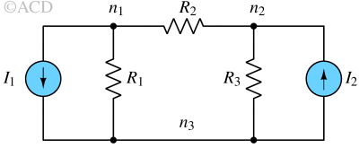
For the circuit mentioned below, we want to calculate the node voltages V1 and V2 for nodes n1 and n2 respectively. After finding node voltages, we can find the current through R1, R2, and R3 as well.

Assigning n3 as the reference node because a lot of components are connected to this node. We can arbitrarily set zero voltage (0V) for node n3. The voltages of n1 and n2 are Vn1 and Vn2 respectively.
By applying KCL at node n1 :
$$\cfrac{V_{n1}}{R_1}+\cfrac{V_{n1}-V_{n2}}{R_2}=-I_1$$
$$V_{n1}\left(\cfrac{1}{R_1}+\cfrac{1}{R_2}\right)-\cfrac{V_{n2}}{R_2}=-I_1$$
By applying KCL at node n2 :
$$\cfrac{V_{n2}}{R_3}+\cfrac{V_{n2}-V_{n1}}{R_2}=I_2$$
$$V_{n2}\left(\cfrac{1}{R_3}+\cfrac{1}{R_2}\right)-\cfrac{V_{n1}}{R_2}=I_2$$
We have two equations and two unknown variables (Vn1 and Vn2). So, we can solve the system of equations above. Sometimes we can represent the KCL equations of node n1 and node n2 in matrix form as shown below:
$$\begin{bmatrix}
(1/R_1+1/R_2) & -1/R_2 \\ -1/R_2 & (1/R_3+1/R_2)
\end{bmatrix} \begin{bmatrix} V_{n1} \\ V_{n2} \end{bmatrix}=\begin{bmatrix} -I_1 \\ I_2\end{bmatrix}$$
Conductance matrix
We can represent the aforementioned matrix as :
$$[G][V]=[I]$$
Where [G] is called the conductance matrix or G-matrix,
$$[G]=\begin{bmatrix}(1/R_1+1/R_2) & -1/R_2 \\ -1/R_2 & (1/R_3+1/R_2)\end{bmatrix}$$
To solve for [V], we can find the inverse of [G] and multiply with [I],
$$[V]=[G]^{-1}[I]$$
Supernode
A super node is a theoretical concept when two non-reference nodes across a voltage source are combined together through a wire to solve nodal analysis.
A SPICE program uses modified nodal analysis to solve a circuit with a voltage source between 2 non-reference nodes.
Example of nodal analysis with a supernode
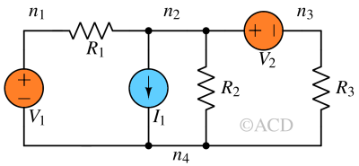
For the circuit mentioned below, we want to calculate the node voltages Vn1, Vn2, and Vn3 for nodes n1, n2, and n3 respectively. After finding node voltages, we can find the current through R1, R2, and R3 as well.

Since we do not know how much current is flowing through V1 and V2, it is hard to apply nodal analysis using KCL directly. We can assign node n4 as the reference node (0V). We will still note down some relations:
$$V_{n2}-V_{n3}=V_2$$
$$V_{n1}-0=V_2$$
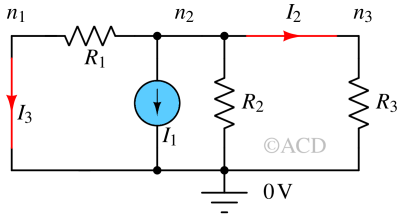
We can redraw the circuit shown in Fig 2. The voltage sources V1 and V2 have been replaced with shorts carrying currents I3 and I2 respectively. The nodes n2 and n3 have been merged to form a supernode (assigning it n2). The nodes n1 and reference node form a supernode (assigning it n1).

Writing KCL equation for node n2:
$$\cfrac{V_{n2}}{R_2}+I_1+I_2+I_3=0$$
Writing KCL equation for node n1:
$$\cfrac{V_{n1}-V_{n2}}{R_1}+I_3=0$$
Writing KCL equation for node n3:
$$\cfrac{V_{n3}-0}{R_3}-I_2=0$$
Solving the system of five equations to obtain Vn2:
$$V_{n2}=\left(\cfrac{V_1}{R_1}+\cfrac{V_2}{R_3}-I_1\right)/\left(\cfrac{1}{R_1}+\cfrac{1}{R_2}+\cfrac{1}{R_3}\right)$$
We already know:
$$V_{n3}=V_{n2}-V_2$$
$$V_{n1}=V_1$$
Modified nodal analysis (MNA)
Modified nodal analysis is a more general way to solve for node voltages. It automatically takes care of voltage sources in the circuit.
Why MNA is useful?
In the former method of addressing networks involving supernodes, a circuit-solving software like SPICE had to individually determine the presence of a voltage source. It's common in simulations to insert a voltage source between two nodes to calculate the current. However, the additional process of identifying the existence of a voltage source between nodes was inefficient.