What is a bandstop or bandreject filter?
A bandstop filter, or a band-reject filter, is an electronic or signal processing filter designed to attenuate a specific range of frequencies within a signal while allowing all other frequencies to pass through relatively unaltered. It is opposite to a bandpass filter, where the bandpass filter passes a specific range of frequencies. A very sharp bandstop filter is sometimes called a notch filter, which removes a very narrowband of frequency.
Frequency response of Bandstop filter

The frequency response of a band-stop filter (Fig 1) is shown in Figure 1. A band-stop filter is designed to attenuate a specific range of frequencies while allowing frequencies outside that range to pass.
The frequency response of a band-stop filter typically has the following characteristics:
- Passband: In this region, the filter has a flat or nearly flat response. These frequencies are considered the “passband” of the filter.
- Stopband: The stopband is the range of frequencies that the filter is designed to block or attenuate.
- Center Frequency (fC): The center frequency of the notch or bandstop is the frequency at which the filter provides maximum attenuation. This is the frequency that the filter is primarily designed to reject.
- Bandwidth: The bandwidth of the bandstop filter is the range of frequencies over which attenuation occurs. It is typically defined as the width of the stopband at -3 dB of attenuation.
- Roll-off rate: The roll-off is the rate at which the filter’s gain decreases as we move away from the center frequency (fc) and into the stopband. The roll-off rate is usually specified in decibels per decade (dB/decade). A steeper roll-off indicates a faster attenuation rate.
- Q Factor (Quality Factor): The Q factor is a measure of the sharpness or selectivity of the bandstop filter. A higher Q factor results in a narrower bandwidth and a sharper notch at the center frequency. Conversely, a lower Q factor results in a wider bandwidth and a shallower notch.
Mathematical representation of band-stop/notch filter
The following equation represents the standard form of a band-stop/notch filter:
$$H(s)=\cfrac{1+\cfrac{s^2}{\omega{}_o^2}}{1+\cfrac{s}{\omega{}_oQ}+\cfrac{s^2}{\omega{}_o^2}}$$
For a notch filter, the value of Q is usually high (Q > 0.707).
Bandstop filter using low-pass and high-pass filter

Fig 2 shows an active-stop filter. It consists of a high-pass filter and a low-pass filter in parallel. The cutoff frequency of the low pass filter is fL. The cutoff frequency of the high pass filter is fH. To make a band-reject / band-stop filter, fL < fH as shown in frequency response in Fig 1. Since it is an active filter, a gain can also be obtained in the pass-band. These kind of architecture usually have low Quality factor (Q).
Notch filter
A notch filter is a special band-stop filter that attenuates or suppresses a specific frequency while allowing other frequencies to pass without significant attenuation. It is designed to create a “notch” or a deep attenuation in the frequency response at a particular frequency, as shown below.

Passive band-stop/notch filter
A passive notch filter attenuates a narrow range of frequencies while allowing all other frequencies to pass through relatively unaltered without requiring an external power source or active components like amplifiers or transistors. Instead, it relies on passive components such as resistors, capacitors, and inductors to achieve the desired frequency response.
Parallel RLC notch filter

Series RLC notch filter

A series LC passive notch filter is shown in Fig 5. At the frequency of ωc=1/√LC the LC tank’s impedance will become zero. At this resonant frequency (fc), Vout is shorted to the ground by the LC tank. At lower frequencies, the capacitor becomes open. At higher frequencies, the inductor opens. The frequency response is similar to the one mentioned in Fig 3.
Twin-T notch filter

A twin-T notch filter is a passive filter circuit used to attenuate a specific frequency from an input signal while allowing all other frequencies to pass through. It has a simple and elegant design with a very low Bill of materials (BOM).
The name “twin-T” comes from the configuration of two “T” shaped RC (resistor-capacitor) networks connected in parallel as shown in Fig 6. The twin-T notch filter is commonly used to filter out interference or noise at a specific frequency, such as 60 Hz hum in power lines or unwanted harmonics/interference in audio signals.
The basic twin-T notch filter circuit consists of the following components:
- Low-pass T-network: It is made using two resistors and a capacitor. To understand, it forms a low pass filter.
- High-pass T-network: It is made using two capacitors and a resistor. To understand, it forms a high pass filter.
Active band-stop/notch filters
Passive notch filters cannot provide gain. Also, the quality factor (Q) of RC twin-T notch filter is maximum 1/2. So, active elements are added e.g., amplifiers to improve the quality factor.

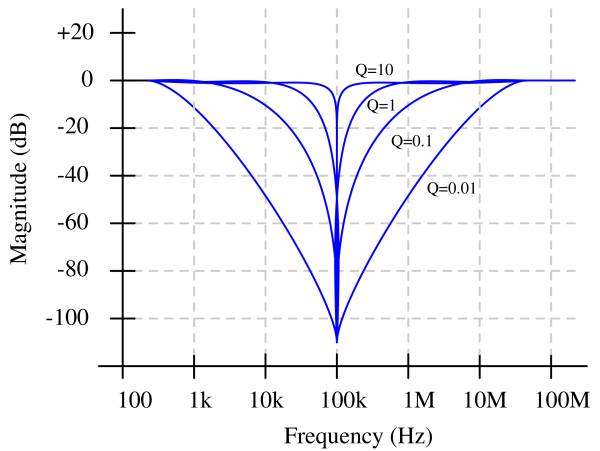
The above figure shows the transfer function of notch filters having different quality factors. It can be observed that higher the quality factor, sharper the rejection. The depth of notch does not depend on the quality factor. What depends on the quality factor is the spread. All the notch filters are designed for 100kHz centre frequency. For Q=0.01, the attenuation starts from 1kHz. For Q=10, the attenuation starts from 90KHz. So, Q=10 is much better notch filter.
Active twin-T notch filter

The Q of the passive twin-T notch filter is low (<1/2). So, an active twin-T notch filter is used to obtain a very high Q. The Q can be raised from the usual 0.3 to something greater than 10. The buffer (using opamp A2) provides a low output resistance; and the high input resistance of the opamp A1 makes it possible to use large resistance values in the ‘‘T’’ network so that only small capacitors are required, even at low frequencies. The addition of opamp overcomes parasitic capacitances which makes it suitable for high-frequency operation. The frequency of the notch is unchanged with the addition of opamps. A 60dB notch can be obtained if 0.1% tolerance resistors and 1% tolerance capacitors are used.
In applications where the rejected signal might deviate slightly from the null of the notch network, it is advantageous to lower the Q of the network. This ensures some rejection over a wider range of input frequencies.
Design equations of Active Twin-T notch filter :
$$\cfrac{v_{out}}{v_{in}}=\cfrac{1+s^2R^2C^2}{1+sRC\cfrac{4}{1+R_G/R_F}+s^2R^2C^2}$$
Quality factor (Q):
$$Q=(1+\cfrac{R_G}{R_F})/4$$
Center Frequency (ωo):
$$\omega{}_o=\cfrac{1}{RC}$$
Some disadvantages of Twin-T filter topology :
It needs eight precision components for desired notch depth. For example, R/2 can be achieved by placing two R resistors in parallel, and 2C by placing two C capacitors in parallel.
- The twin-T topology is not well-suited for single-supply operation and is incompatible with fully differential amplifiers.

The above figure shows the effect of component mismatch on the notch attenuation. For 10% component mismatch, the notch attenuation is merely 5dB. It reaches >35dB for 0.1% component mismatch.
Multi-feedback bandstop filter (Implementation 1)

$$H(s)=\cfrac{R_4}{R_3+R_4}\left[\cfrac{s^2+Ks+\cfrac{1}{R_1R_2C_1C_2}}{s^2+\cfrac{C_1+C_2}{R_2C_1C_2}s+\cfrac{1}{R_1R_2C_1C_2}}\right]$$
Where K,
$$K=\cfrac{R_1(C_1+C_2)-R_2C_2\cfrac{R_3}{R_4}}{R_1R_2C_1C_2}$$
For a bandstop response, K should be zero. That will convert the above equation into band stop filter standard form. To simplify the design, we assume C1 = C2 = C. Substituting it in above equation, we get :
$$\cfrac{R_3}{R_4}=\cfrac{2R_1}{R_2}$$
The cut-off frequency (ωo) and quality-factor (Q) :
$$\omega{}_o=\cfrac{1}{\sqrt{R_1R_2C_1C_2}}$$
$$Q=\cfrac{1}{2}\sqrt{\cfrac{R_1}{R_2}}$$
Multi-feedback bandstop filter (Implementation 2)

$$H(s)=\cfrac{R_6}{R_5}\cfrac{sC_1R_2R_3/(R_1+R_3)}{s^2C_1C_2R_1R_2R_3/(R_1+R_3)+sR_1R_3(C_1+C_2)/(R_1+R_3)+1}-\cfrac{R_6}{R_4}$$
For bandstop response, following condition should be met:
$$R_4=\cfrac{R_1R_5(C_1+C_2)}{R_2C_1}$$
Center-Frequency (ωo) and Quality factor (Q):
$$\omega{}_o=\cfrac{1}{\sqrt{C_1C_2R_2(R_1||R_3)}}$$
$$Q=\cfrac{\sqrt{\cfrac{C_1C_2R_2}{R_1||R_3}}}{(C_1+C_2)}$$
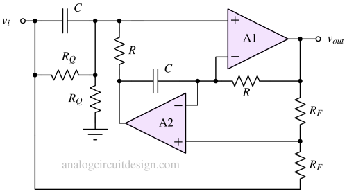
Fliege notch filter

This circuit offers the following features:
- Tuning the center frequency requires only four precision components—two resistors (R) and two capacitors (C). A key advantage of this circuit is its tolerance to slight component mismatches: while the center frequency may shift, the notch depth remains unaffected.
- The filter’s Q factor can be adjusted independently of the center frequency by using two equal-value, noncritical resistors.
The design equations of Fliege notch filters are :
$$\omega{}_o=\cfrac{1}{RC}$$
$$Q=\cfrac{R_Q}{R}$$
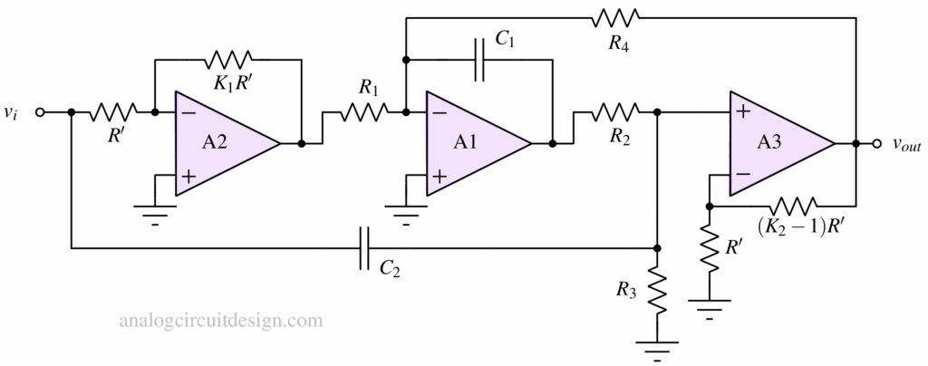
Bainter Notch filter

This design, shown in above figure, has several notable features. The notch Q is determined by the amplifier gains rather than precise component matching. As a result, the notch depth remains stable over temperature variations and aging. Even if the notch frequency shifts, the depth is largely unaffected. Moreover, the circuit exhibits low component sensitivity around 0.5.

The circuit consists of three simple amplifier blocks and two feedback loops. The right hand side of C2 is a high pass response. The output of A1 is a low pass response. A3 functions as a summing amplifier, producing the complete notch filter output. R4 alters the Quality-factor of the notch response.
