Op Amp circuits and applications
Operational amplifiers (Op Amps) are incredibly versatile components used in various electronic applications due to their ability to amplify signals with high precision and low distortion. Some common Op Amp circuits are:
- Positive gain amplifier and Negative gain amplifier
- Voltage adder and subtractor
- Voltage follower (Buffer)
- Voltage integration and differentiation
- Precision rectifier
- Active filters
- Voltage to current converter or Current to voltage converter
- Voltage peak detector
- Comparator
Non-inverting amplifier and inverting amplifier
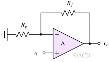
A non-inverting operational amplifier (op-amp) circuit produces an output voltage in phase with the input voltage's phase. In contrast, its counterpart, the inverting op-amp, generates an output signal 180 degrees out of phase with the input.
The non-inverting amplifier's gain is determined by the feedback resistor (Rf) ratio to the input resistor (Rg). The gain (Av) is calculated using the formula:
$$A_v=1+\cfrac{R_f}{R_g}$$
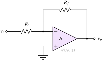
An inverting operational amplifier, or op amp, is a circuit where the output voltage moves in the opposite direction compared to the input voltage. In simpler terms, it operates out of phase by 180°.
The inverting amplifier's gain is determined by the feedback resistor (Rf) ratio to the input resistor (Rg). The gain (Av) is calculated using the formula:
$$A_v=-\cfrac{R_f}{R_i}$$
Voltage addition
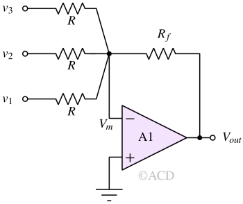
Also known as the adder, the summing amplifier produces a voltage output equivalent to an amplified sum of two or more input voltages. Usually, a summing amplifier is made using an inverting operational amplifier. The expression for output voltage (Vout) is :
$$V_{out}=-\cfrac{R_f}{R}\left(v_1+v_2+v_3\right)$$
Voltage subtraction
Voltage subtraction can be achieved using Difference amplifiers. Difference amplifiers amplify the difference between two input voltages, distinguishing this operational amplifier circuit as a subtractor, in contrast to a summing amplifier, which combines input voltages. The Differential Amplifier is shown below:

$$V_{out}=\cfrac{R_2}{R_1}\left(V_{ip}-V_{im}\right)$$
In the above circuit, the output voltage is precisely equal to R2/R1. This makes the output very reliable because the gain factor is known. Now, if we recall, the Op Amp is itself a difference amplifier (without R1 or R2). So, why not just use an Op-Amp without configuring it in a negative feedback manner as shown above? This is because the gain factor (open-loop gain) is not controlled in Op Amp. It is very high but fluctuates a lot with temperature, voltage, humidity, etc. So, the open-loop gain is unreliable.
Voltage Integration
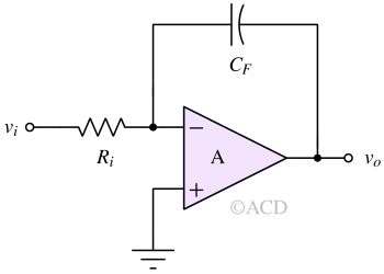
An op-amp integrator uses an operational amplifier (Op Amp), a resistor, and a capacitor to execute the mathematical function of integration. In operation, an op-amp integrator generates an output voltage directly proportional to the integral of the input voltage. Consequently, the output voltage not only depends on the input voltage magnitude but also on the time duration. The output voltage expression for a basic opamp integrator in mentioned below:
$$v_{o}(t)=-\int_{-\infty{}}^{t}\cfrac{v_i}{R_iC_F}dt$$
Please note the negative sign. The configuration is similar to an inverting amplifier. The DC gain is infinite if the operational amplifier used is ideal.
Voltage differentiator
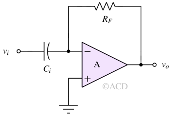
The differentiator op-amp setup produces an output voltage directly proportional to the rate of change of the input voltage.
$$v_o=-R_FC_i\cfrac{dv_i}{dt}$$
Precision rectifier
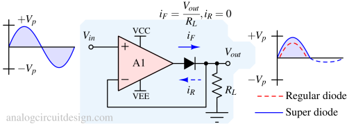
As shown above, it is used in precision rectifier circuits where the diode drop is removed from the output voltage. Read more - Precision rectifier.
Active filters
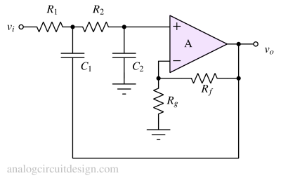
Unlike passive filters, which use only passive components like resistors, capacitors, and inductors, active filters incorporate active components like operational amplifiers (op-amps) to achieve desired filtering characteristics. These filters offer advantages such as better control over filter parameters, higher gain, and improved performance. Two very important characteristics of an active filter :
- Gain - The gain can be higher than 1V/V.
- Quality factor - The quality factor can be greater than 0.707 in an active filter. The maximum quality factor achieved in a passive filter is 0.707, which needs some conditions to be satisfied.
Voltage to current converter
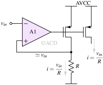
Op Amp can create voltage to current converters using MOSFETs and BJTs. MOSFETs are good voltage-controlled current sources. However, we don't know how much voltage there should be at the gate for a required current. This problem can be easily solved using an Op Amp, as shown in Fig 9. We can force a voltage across a resistor; the resistor value is chosen to get the required current for a given voltage. The Op Amp will set the gate voltage of the MOSFET. This gate voltage can be applied to another MOSFET to get the desired vin/R current.
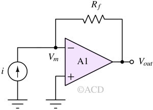
Current to voltage converter (transimpedance amplifier)
A transimpedance amplifier (TIA) is an operational amplifier (op-amp) circuit configuration that converts an input current signal into an output voltage signal. It's particularly useful for applications involving photodiodes, phototransistors, or other current-generating sensors.
Voltage peak detector
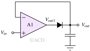
Peak detectors are designed to record the highest or lowest voltage points in a signal. A positive peak detector records the highest positive voltage, while a negative peak detector records the lowest negative voltage. A diode and capacitor-based peak detector will have a diode drop (-0.7V) at the output voltage. This reduces the accuracy of the peak detector. An Op Amp can be used, as shown above, to remove the diode drop and increase the precision.
Comparator
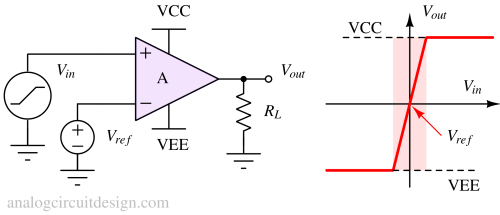
Typically, comparators are built using dedicated comparator integrated circuits (ICs), although operational amplifiers (op-amps) can be an alternative if speed and power are not a concern. Both comparator and op-amp diagrams employ identical symbols.
The above figure shows a comparator circuit. Note that the circuit does not use feedback. The circuit amplifies the voltage difference between Vin and VREF and outputs the result at Vout. If Vin exceeds VREF, the Vout voltage will reach its positive saturation level (near VCC). If Vin is lower than VREF, Vout will fall to its negative saturation level (near VEE).