Op Amp based comparator
A comparator is an electronic circuit that compares the voltage levels of two input signals and produces a binary output indicating which input is higher. We can use an operational amplifier as a comparator configuring it in open-loop. Open-loop means there is no negative feedback. The op-amp is allowed to saturate to its maximum and minimum output levels.
Typically, it outputs a high voltage level (e.g., VCC) when the non-inverting terminal's voltage is greater than the inverting terminal's voltage. It outputs a low voltage level (e.g., VEE or ground) when the inverting terminal's voltage is higher than the non-inverting terminal.
Opamp in open loop configuration
Op-Amp comparators have a high voltage gain, which means they amplify the small differences between input signals to produce a clear digital (saturated) output.
Positive comparator

A positive comparator is a comparator configuration where the input signal is connected to the non-inverting input (+) and the reference voltage is applied to the inverting input (−).
Working :
- When the input signal > reference voltage, the output goes high (logic 1 or +Vcc)
- When the input signal < reference voltage, the output goes low (logic 0 or VEE).
The output is moving in the direction of the input signal — hence called positive comparator.
Negative comparator

A negative comparator is a comparator configuration where the reference voltage is applied to the non-inverting input (+), and the signal input is connected to the inverting input (−).
Working :
- When the input signal > reference voltage, the output goes low (logic 0 or VEE).
- When the input signal < reference voltage, the output goes high (logic 1 or +Vcc).
The output is going in opposite direction of the input signal — hence called negative comparator.
Disadvantages of using op amp as comparator
- While op-amps can be used as comparators, dedicated comparator ICs are specifically designed for this purpose. They offer faster response times and lower propagation delays, often without increasing power consumption or cost. However, unlike op-amps, comparator ICs are not suitable for linear amplification and cannot be used as op-amps.
- The main limitation of opamp is the compensation capacitor which limits the rise time when used as a comparator. The compensation capacitor is added in opamp to ensure stability and prevent excessive output voltage ringing in negative feedback mode. There is no such compensation capacitor in a comparator.
- The recovery through saturation is not optimised in opamp.
- Many opamps which are optimised for higher bandwidth operation don’t support large differential voltage across its inputs. This is because to protect the input transistor from overvoltage, there are back to back diodes which can demand a lot of current when we try to force large differential voltage at the inputs.
- Opamps do not have internal hysteresis so may not be suitable for comparator application in noisy environment. However, an opamp can be converted into Schmitt trigger to add hysteresis.
Window comparator
A window comparator is a circuit that uses two comparators to check whether an input voltage lies within a specific voltage range (window) or outside of it. The range of voltage is decided by two reference voltages (Vref1 and Vref2). It utilizes two comparators in parallel (positive and negative comparators) with open collector BJTs.

Op-amps can be used as comparators, as illustrated in Fig. 3. The upper op-amp activates the upper BJT when the input voltage exceeds Vref2, pulling the output node low. Similarly, the lower op-amp activates the lower BJT when the input voltage drops below Vref1, pulling the output low. When the input voltage stays between Vref1 and Vref2, both op-amps output low, keeping both BJTs off. In this case, no current flows through the resistor, so the output remains high.
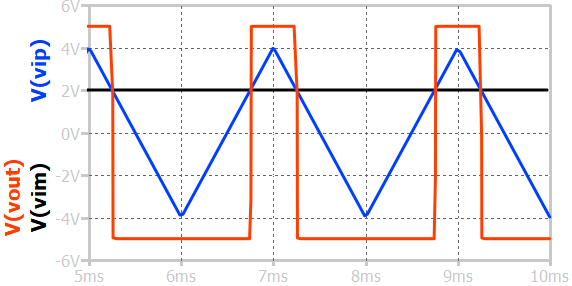
Op amp comparator waveform

In the above figure, an op-amp is configured as a positive comparator. The signal voltage is attached to the non-inverting pin of the opamp (VIP), and the reference voltage is attached to the inverting pin of the opamp (VIM). The supply voltage is +5V and -5V. This means that the output voltage (VOUT) can go to a maximum of +5V and -5V.
Op amp comparator with hysterisis
The noise in the input signals (vip) leads to numerous transitions at the output (vout), as depicted below. This scenario is undesirable as it may cause multiple transitions at the output for a supposedly single event. The block next to such a comparator will see multiple edges. If an FSM is connected to the output of such a comparator, it will jump many states, resulting in failures.
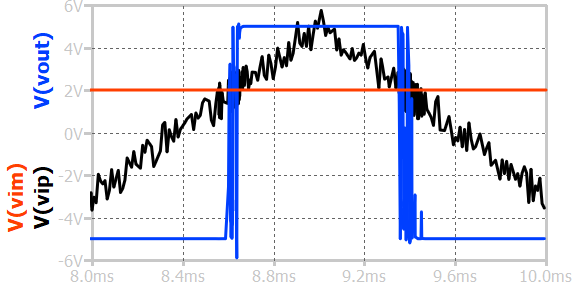
The solution to such a problem is to use a comparator with hysteresis. As soon as the first transition happens at the output voltage, the comparator's trigger voltage (or reference) is changed. If the voltage hits the previous threshold again due to noise or glitch, the output won't change because the present threshold is different.
