Power factor and Power factor correction (PFC)
Electricity primarily travels through AC waveforms, and the efficiency of this transmission is quantified using the power factor. This factor is derived by dividing the average power by the "apparent" power. The apparent power is computed by multiplying the RMS values of voltage and current independently.
When voltage and current are perfectly aligned in phase, as with sine waves, the power factor is 1, indicating highly efficient power transmission. However, as the phase relationship between voltage and current shifts, the power factor diminishes, reaching zero for a 90-degree shift. In most AC circuits there is never a power factor equal to one because there is always some reactive impedance on the power lines.

Impact of power factor
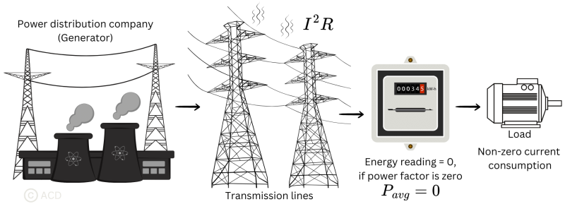
When the power factor is low, the RMS current through the transmission lines is high. This leads to higher I2R losses in the transmission lines. The energy company charges only for the energy meter reading, not the I2R losses incurred in the transmission lines. The energy meter reading is the real power. Consequently, the company incurs the expense of energy lost during transmission. When this occurs on a larger scale, it results in losses for energy companies. It places strain on the power grid as the demand for current has risen, despite the actual power requirement from the consumer side being low.
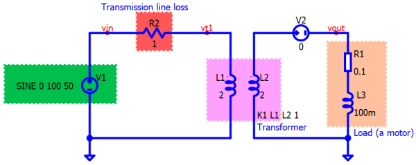
To understand this better, consider the example below where a scenario is modeled. The load (motor) is modeled using an inductor (L3) and a series contact resistor (R1).

Table 1: Power distribution with reactive loading | Power loss in transmission | 6.06W | | --- | --- | | Average power in the meter | 1.06W |
Table 1 summarises the power distribution with a typical load that is reactive. It shows that while the energy meter reads a power of 1.06W, the losses incurred in the transmission line 6.06W.
Reasons of Low Power Factor
Some very common reasons for low power factor are mentioned below :
Inductive load
Induction motors comprise 90% of industrial loads, causing current to lag behind voltage, consequently operating at a low power factor. The lagging current drawn by these inductive loads leads to a lower power factor.
Imbalance in 3-phase windings
An imbalance in the 3-phase power can result in a low power factor due to inadequate wiring or electrical mishaps.
Change in Frequency of supply
Most of the PFC correction methods are designed for a particular frequency (50Hz or 60Hz). At this frequency, the power factor is maximum. A change in frequency reduces the power factor.
Harmonics
Harmonics originate from nonlinear loads, which refer to circuit elements drawing current in a way that deviates from a sinusoidal pattern.
Table 2: Linear and non-linear loads | Linear Loads | Non-Linear loads | | --- | --- | | Some motors, Incandescent Lighting, Heating loads | DC drives, Variable frequency drives, Programmable controllers, Induction furnaces, Solid-state power supplies |
What is power factor correction (PFC)?
To tackle the problem of unaccounted I²R losses in transmission lines caused by a poor power factor on the consumer’s end, the power company keeps track of the power factor at the consumer’s location. If it drops below a specified level, penalties are imposed. This monitoring and penalty system encourages consumers to maintain a higher power factor, minimizing losses for the company due to wastage from the consumer's end and improving overall system efficiency.
Using capacitor banks across inductive loads
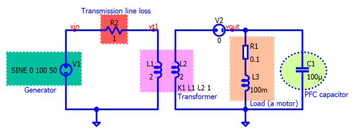
Including a capacitor in parallel with the inductive load serves to reduce the reactive power and concurrently lessen the overall current drawn from the power supply source. Theoretically, capacitors have the potential to offer the entirety of the necessary compensated reactive power in a circuit. However, practically achieving a power factor correction ranging between 95% and 98% (0.95 to 0.98) is typically satisfactory.

Table 3: Power distribution after power factor correction | Power loss in transmission | 0.51W | | --- | --- | | Average power in the meter | 1.06W |
Table 3 summarises the power distribution with the same load as in Fig 2 but with power factor correction. The final implementation with power factor correction is shown in Fig 3. It shows massive improvement in the transmission line loss. It has dropped from 6.06W to 0.51W.

The main reason for such massive improvement is due to the lowering of current in the transmission line. Current through R2 is shown in the above figure (Fig 4) and a comparison is made between "with PFC" and "without PFC". The amplitude of the current dropped significantly when PFC was added.