PWM - Pulse Width Modulation
PWM stands for Pulse width modulation. PWM is also known as pulse-duration modulation (PDM) or pulse-length modulation (PLM). It is a technique used in electronics to encode analog information in form of duty cycle of periodic pulses. It is a common technique used to control the power delivered to electronic devices. Most common applications are motor speed control, light dimming, and voltage regulation in switching regulators.

In a PWM system, the signal consists of a series of pulses with varying widths. The pulse's time period is constant. The term "pulse width" refers to the duration of time the signal is in the high (on) state within each cycle.
PWM Characteristics
A PWM signal serves as a means to generate digital pulses for regulating analog circuits. Its behavior is primarily characterized by two key components:
- Duty Cycle
- Frequency and Time period
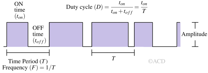
Duty cycle
A duty cycle represents the portion of one cycle during which a system or signal is active. It's commonly conveyed as a ratio or percentage. A period (T) denotes the duration required for a signal to complete a full ON-OFF cycle. When the signal is in its high state, we denote it as ON and the time duration for which the waveform is in ON state is called Ton. The time duration for which the waveform is in OFF state is called Toff. Basically Ton + Toff = T. The duty cycle (D) represent the fraction of time the signal is in ON state out of total time period. It is the ratio of Ton and T.
$$D=\cfrac{T_{on}}{T_{on}+T_{off}}=\cfrac{T_{on}}{T}$$
For example, a digital signal that maintains an equal division between ON and OFF states, resulting in a half-and-half distribution, possesses a 50% duty cycle, resembling an ideal square wave. Conversely, a signal that spends three-quarters of its time in the ON state and one-quarter in the OFF state exhibits a duty cycle of 75%.
Frequency and Time period
The frequency refers to how often something repeats or happens within a specific timeframe. It specifically pertains to the rate of vibration that generates a wave, such as sound, radio, or light waves, usually measured per second. Frequency plays a crucial role in PWM's effectiveness in controlling an application. Hence, the square wave frequency must be sufficiently high, particularly when managing LEDs, to achieve the desired dimming effect.
For instance, a duty cycle of 50% at 1 Hz would be perceptible to the human eye, indicating the LED's alternating ON and OFF states. However, with a frequency of 100 Hz or above, the same 50% duty cycle would result in half-intensity light.
Converting PWM signal into analog signal
Pulse-width modulation employs a square or rectangular wave where the width of the pulses is modulated while keeping the time period of the waveform unchanged. This leads to changes in the average value of the waveform.

Let's assume the function is f(t), the OFF state voltage is Vlow, the ON state voltage is Vhigh, the time period is Tperiod, the ON state time is Ton, and the OFF state time is Toff. The relation between average output voltage and duty cycle is :
$$\overline V_{out}=D\cdot{}V_{high}$$
Derivation : Output voltage and Duty cycle relation
We can find the average using the integral function as shown below:
$$\overline V_{out}=\cfrac{1}{T}\int_{0}^{T}f(t)\cdot{}dt$$
$$\overline V_{out}=\cfrac{1}{T}\left[\int_{0}^{t_{on}}V_{high}\cdot{}dt+\int_{0}^{t_{off}}V_{low}\cdot{}dt\right]$$
$$\overline V_{out}=\cfrac{V_{high}\cdot{}t_{on}+V_{low}\cdot{}t_{off}}{T}$$
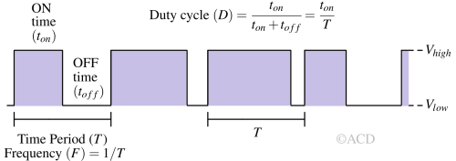
We can write the above expression in terms of duty cycle (D) as follows:
$$\overline V_{out}=D\cdot{}V_{high}+(1-D)\cdot{}V_{low}$$
Most of the time, Vlow equals 0V, so :
$$\overline V_{out}=D\cdot{}V_{high}$$
We can find the average using the integral function as shown below:
$$\overline V_{out}=\cfrac{1}{T}\int_{0}^{T}f(t)\cdot{}dt$$
$$\overline V_{out}=\cfrac{1}{T}\left[\int_{0}^{t_{on}}V_{high}\cdot{}dt+\int_{0}^{t_{off}}V_{low}\cdot{}dt\right]$$
$$\overline V_{out}=\cfrac{V_{high}\cdot{}t_{on}+V_{low}\cdot{}t_{off}}{T}$$

We can write the above expression in terms of duty cycle (D) as follows:
$$\overline V_{out}=D\cdot{}V_{high}+(1-D)\cdot{}V_{low}$$
Most of the time, Vlow equals 0V, so :
$$\overline V_{out}=D\cdot{}V_{high}$$
Example of PWM with different duty cycles

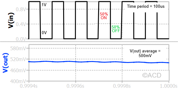
If a PWM waveform is passed through a low pass filter, the filter attenuates its harmonics to generate a DC output voltage. As shown above, the DC output voltage is the average voltage of the PWM waveform for a 35% duty cycle waveform.
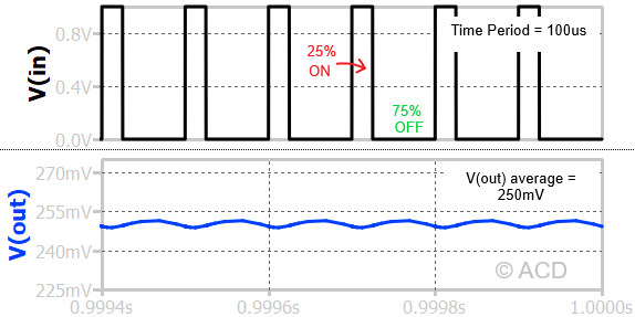
The above figure shows that the ON state time is 25% of the time period of the waveform. This means the duty cycle (D) is 0.25 or 25%. If the V(in) is passed through a low pass filter with a cutoff frequency much lower than 1/Tperiod, we get an average output voltage equal to around 250mV. The input high voltage is 1V, and the low voltage is 0V. This is in accordance with our findings in the previous section, where we concluded that the average is DVhigh.
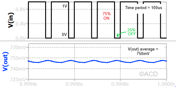 The above figure shows that the ON state time is 75% of the time period of the waveform. This means the duty cycle (D) is 0.75 or 75%. The average output voltage equals around 750mV, which is again equal to 0.75 X 1V (DVhigh).
Types of PWM based on edges
There are two edges on a PWM.
- Leading Edge
- Trailing Edge
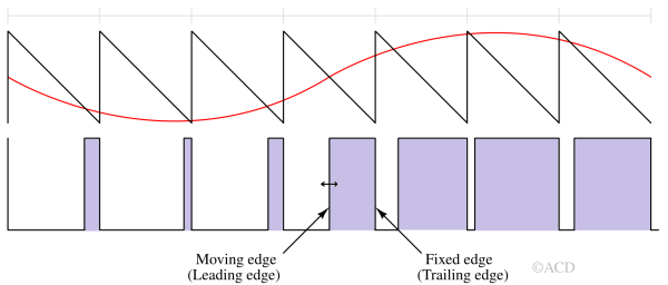
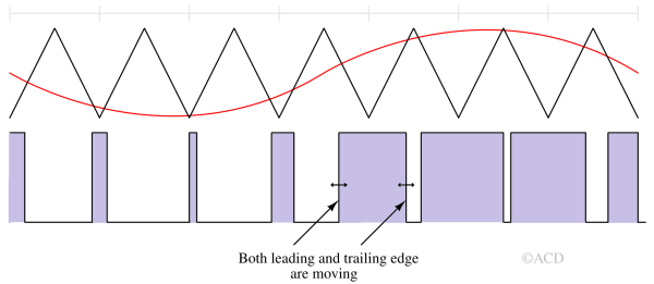
The leading edge refers to the rising edge of the PWM signal, while the trailing edge refers to the falling edge. The modulation type is determined by which edge of the PWM waveform moves.
Leading edge modulation
In leading-edge modulation, the pulse or waveform's leading edge is modulated while the trailing edge remains fixed. As shown in the figure, this modulation uses a negative sawtooth waveform as a carrier/reference waveform.
Trailing edge modulation
In Trailing-edge modulation, the pulse or waveform's trailing edge is modulated while the leading edge remains fixed. This modulation uses a positive sawtooth waveform as a carrier/reference waveform. 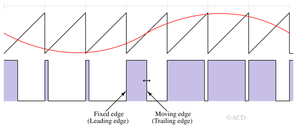
Dual edge modulation
Dual Edge Modulation is a technique used in PWM that modifies the timing of both the leading and trailing edges of the PWM signal. This modulation technique uses a triangular waveform instead of a sawtooth waveform as a carrier/reference waveform.
PWM generators and controllers
There are many ways to generate PWM signal. Some of them are mentioned below:
PWM using Timer 555
The astable multivibrator mode of timer 555 is modified to create a PWM generator. VR1 is a variable resistor (potentiometer) added between R1 and R2 to vary the duty cycle. Values of R1, R2, VR1, and C determine the frequency of the PWM signal's output.
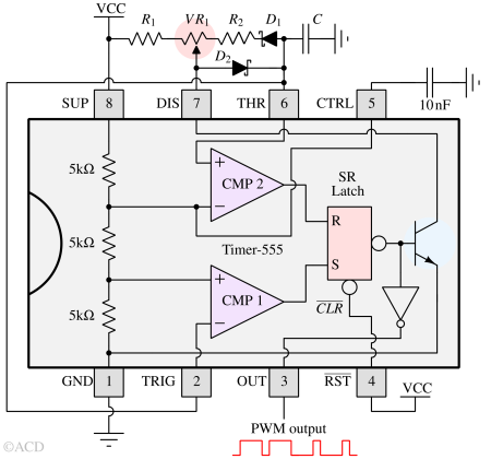

Working principle of Timer 555 based PWM generator
Let’s refer to the figure above. It is pretty interesting to understand how the timer 555 based PWM generator works. Capacitor (C) is charged using R1, VR1, and D2. The maximum voltage it would be charged to is (2/3)VCC. It will trigger comparator 2 (CMP2), resetting the internal SR-latch and pulling down the discharge pin (DIS) using the internal NPN transistor. Now, discharging is taking place. The discharge path is D1, R2, and VR1. The discharge will happen until the THR pin voltage falls to (1/3)VCC. It will trigger comparator 1 (CMP1), setting the internal SR-latch and disabling the discharge by grounding the internal NPN’s base. The discharge of C determines the off-time (Toff) of the output PWM waveform (coming at the OUT pin), and the charging of C determines the on-time (Ton).
Ton :
$$\cfrac{2}{3}\text{VCC}=\text{VCC}+\left(\cfrac{1}{3}\text{VCC}-\text{VCC}\right)e^{-\cfrac{T_{on}}{(VR_1+R_1)\cdot{}C}}$$
$$T_{on}=ln{(2)}(VR_1+R_1)\cdot{}C$$
Toff :
$$\cfrac{1}{3}\text{VCC}=0+\left(\cfrac{2}{3}\text{VCC}-0\right)e^{-\cfrac{T_{off}}{(VR_2+R_2)\cdot{}C}}$$
$$T_{off}=ln{(2)}(VR_2+VR_2)\cdot{}C$$
Frequency (F):
$$F=\cfrac{1}{T_{on}+T_{off}}=\cfrac{1}{ln{(2)}\cdot{}(R_1+R_2+VR_1+VR_2)\cdot{}C}$$
The frequency is constant because VR1+VR2 is a fixed value, which is the total end-to-end resistance of the variable resistance (VR1).
Duty cycle :
$$\text{D}=\cfrac{T_{on}}{T_{on}+T_{off}}=\cfrac{VR_1+R_1}{VR_1+VR_2+R_1+R_2}$$
PWM using opamps
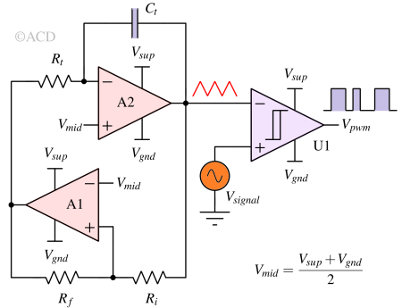
Opamps can be used to generate the triangular waveform, which serves as one of the inputs of the final comparator (U1). Opamps A1 and A2 generate the triangular waveform together. A2 is an integrator, and A1 is configured in a positive feedback manner to generate a square wave. Comparator U1 can be made using an opamp as well. The non-inverting terminal has the signal, while the inverting terminal has the triangular waveform. The output of U1 produces a dual-edge modulation type of PWM.
PWM using TL494
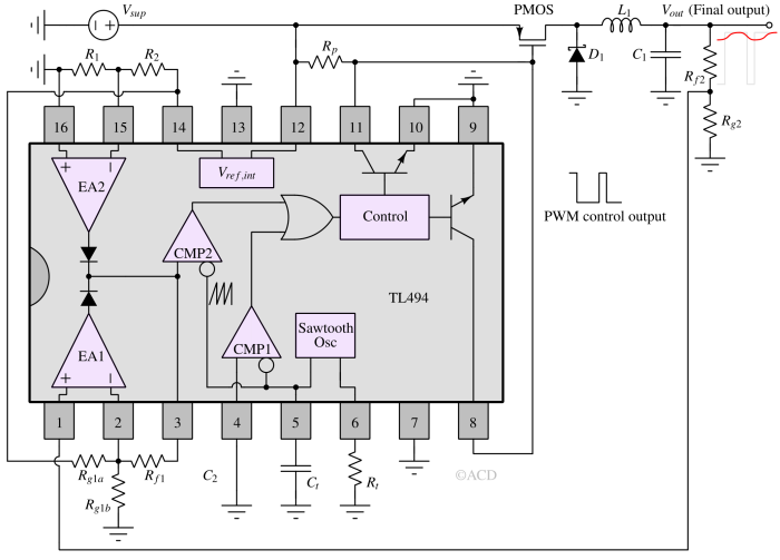
TL494 integrated circuits are very popular in power supplies and DC-DC switching regulators. Other ICs, e.g., UC3843 and TL594, are also available as PWM controllers. TL494 has an inbuilt error amplifier, comparator, positive sawtooth generator, reference voltage, and high-current drive NPNs. These types of ICs can be used as controllers for buck regulators, as shown in following figure.
Working principle of TL494 PWM generator IC
As with any other PWM generator, TL494 has a comparator and sawtooth generator, which generate the PWM control waveform. The PWM control waveform controls the gate of the pass transistor (PMOS). The drain of the PMOS is connected to a low-pass filter made using L1 and C1. D1 is a freewheeling diode that prevents voltage spikes when the PMOS is turned off. TL494 also has two error amplifiers, EA1 and EA2, which can regulate voltage and load current, respectively. A 5V internal voltage reference (Vref,int) can set the output voltage to the desired voltage. In the following figure, only voltage regulation is done. EA1 is configured as a non-inverting amplifier having a transfer function :
$$V_{EA1}=(V_{out}-V_{ref})\cdot{}G$$
The G is the gain, which depends on the resistors. The gain should be high (e.g., > 40) for good accuracy.
Pulse Modulation or Pulse Wave Modulation
There are other types of modulation in which the message signal may be either analog or digital, while the carrier signal is always digital, typically in the form of a pulse train. When an analog message signal is combined with a digital (pulse) carrier, the process is called analog pulse modulation. When a digital message signal is used with a digital carrier, it is referred to as digital pulse modulation. Based on the three characteristics of a pulse-type carrier, analog pulse modulation is classified into three types, namely:
- Pulse Amplitude Modulation (PAM)
- Pulse Width Modulation (PWM) - Discussed in this article
- Pulse Position Modulation (PPM)
- Pulse Code Modulation (PCM)
Pulse Amplitude Modulation (PAM)
It is the process in which the amplitude of rectangular pulses varies according to the instantaneous value of the sinusoidal (modulating) signal.
Pulse Position Modulation (PPM)
It is the process in which the position of the pulses, or the spacing between them, varies in accordance with the instantaneous value of the sinusoidal (modulating) signal.
Pulse Code Modulation (PCM)
It is the process in which a digital (pulse-type) carrier signal varies according to the digital or binary representation of a sinusoidal message (modulating) signal.
Applications of PWM
- Delta-sigma modulator
- DC-DC switching regulators
- Speed control of DC motors
- Servo motor control
- Class-D amplifiers
- LED brightness control