R-2R Ladder DAC
The R-2R resistor ladder as the name suggest is a network of resistors which has resistors of only two denominations, R and 2R. This network performs a direct conversion of a parallel digital data into an analog voltage. Each digital bit, such as b0, b1, and so on, makes a distinct weighted contribution to the resulting analog output.

Advantages of R-2R ladder based DAC
The advantages of R-2R ladder are:
- Easily scalable to any desired number of bits. Each bit adds 2 resistors (one is R and another is 2R).
- Uses only two values of resistors which make for easy and accurate fabrication and integration.
- Output impedance is always R irrespective of the digital code.
Working of R-2R ladder digital to analog converter
Through a systematic application of Thevenin Equivalent circuits and the Superposition method, we can readily demonstrate the operation of the R-2R circuit.
1-bit R-2R DAC
To start understanding the R-2R, let's consider a single bit resistor network. It is a resistor-divider network with 2R and 2R resistance. The input is a digital input connected either to 0 (GND) or Vref. The output is 0 if the input is connected to 0. The output is Vref/2 if the input is connected to Vref. We can say that the output is b0/2. b0 represents the input of the 1-bit R-2R DAC.
$$V_{\text{1-bit}}=\cfrac{b_0}{2}$$
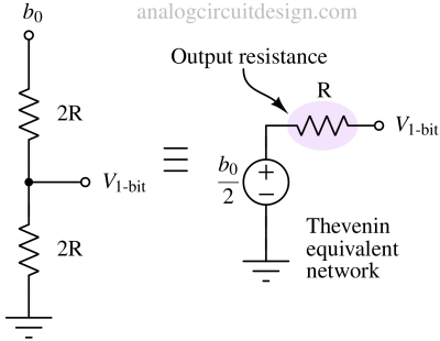
A Thevenin equivalent circuit is mentioned. It shows that the input is represented by a voltage source. The Thevenin equivalent resistance R is connected in series with the voltage source. This Thevenin resistance is also sometimes called the output resistance of the network.
2-bit R-2R DAC
We saw in the 1-bit R-2R ladder that the output resistance is R. To add another bit, we need to add another R and 2R in series with the 1-bit R-2R DAC as shown in the figure. Using superposition theorem, we can see that the output is (b0/2)/2 when b1 is zero and it is b1/2 when b0/2 is zero. So, overall output is:
$$V_{\text{2-bit}}=\cfrac{b_1}{2}+\cfrac{V_{\text{1-bit}}}{2}=\cfrac{b_1}{2}+\cfrac{b_0}{4}$$
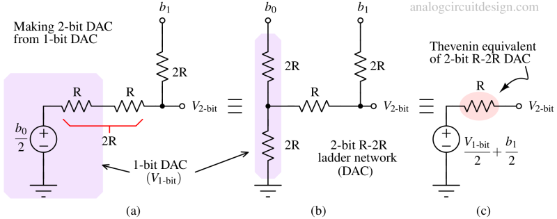
The Thevenin equivalent of the 2-bit R-2R shows that the output resistance is still R as in case of 1-bit R-2R. This constant value of output resistance helps to add bits easily.
3-bit R-2R DAC
We saw in the 2-bit R-2R ladder that the output resistance is R. To add 3rd bit, we need to add another R and 2R in series with the 1-bit R-2R DAC as shown in the figure. Using superposition theorem, we can see that the output is V2-bit/2 when V2 is zero and V2/2 when V2-bit is zero. So, overall output is:
$$V_{\text{3-bit}}=\cfrac{b_2}{2}+\cfrac{V_{\text{2-bit}}}{2}=\cfrac{b_2}{2}+\cfrac{b_1}{4}+\cfrac{b_0}{8}$$
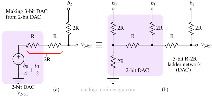
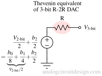
The output resistance is still R. We can add more R and 2R resistor to create N-bit DAC.
N-bit R-2R DAC
If we extend the pattern of 3-bit DAC to N-bit DAC, the output VN-bit can be written as:
$$V_{\text{N-bit}}=\cfrac{b_{N-1}}{2}+\cfrac{b_{N-2}}{4}+\dots{}+\cfrac{b_2}{2^{N-2}}+\cfrac{b_{1}}{2^{N-1}}+\cfrac{b_{0}}{2^N}$$
An N-bit DAC has N-bit inputs. It has N+1 number of 2R resistors and N-1 number of R resistors. So, in total of 3N+1 number of R resistors.

Example output waveform of a R-2R DAC
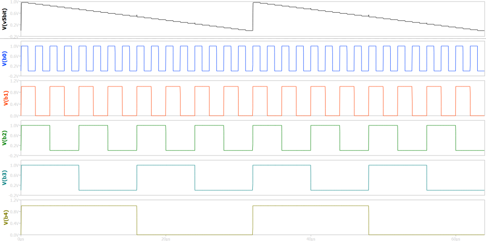
An example waveform is shown for a R-2R ladder in next figure. The digital bits are set to generate ramp waveform. The output has a staircase structure which is inherent to any DAC.
Difference between Binary weighted and R-2R ladder DAC
A binary weighted DAC has resistors from R to R/2N-1 connected to each input. Every resistor has unique value. If we try to use single value of resistor R in Binary weighted DAC, the MSB will have 2N-1 resistors while the LSB will have only one resistor and 2N-1 number of total resistors.
For example, an 8-bit binary weighted DAC has 255 numbers of resistors each valued at R. In contrast, an 8-bit R-2R ladder has only 25 (3N+1) number of resistors each valued at R. This is a huge difference in number of resistors. For higher number of bits, the difference grows exponentially. So, an R-2R ladder occupies less area in PCB or inside a chip.