RC phase shift harmonic oscillator
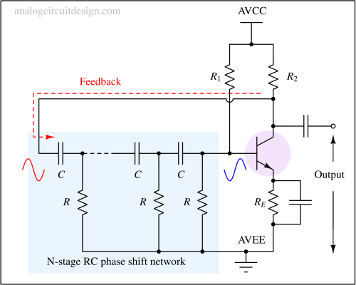
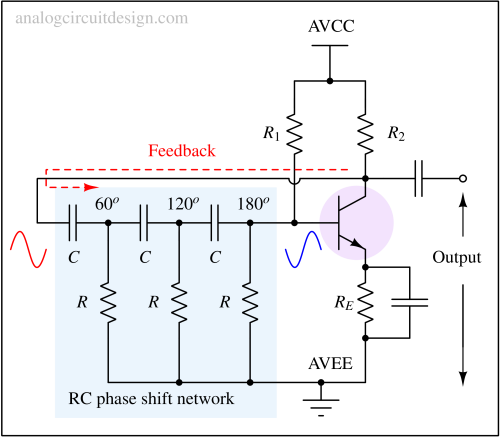
In an RC phase shift oscillator, the primary RC network consists of cascade of RC filters which is designed to provide 180° phase shift in total. The amplifier provides a rest 180° of phase shift to satisfy Barhausen's criteria of sustained oscillations.

$$f_{osc}=\cfrac{1}{2\pi{}RC\sqrt{2N}}$$
Operation of RC phase shift oscillator

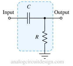
The phase shift by a single-stage RC stage at a frequency ω is :
$$\phi{}=\tan{}^{-1}\left(\cfrac{1}{\omega{}RC}\right)$$
A single-stage RC phase shift circuit can provide a maximum of 90°. We need a total of 180o of phase at our desired frequency.

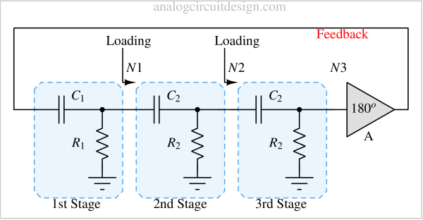
In reality due to loading from the next stage, the phase shift is not precisely tan-1(1/ωRC). Since every stage's loading is different, the phase shift is also different for each stage. However, the total phase shift from the cascade of three stages will still be 180o.

Why not a two-stage RC phase oscillator ?
We may think that having a cascade of two such single-stage RC phase circuits is enough to provide 180o phase shift. But, the required frequency is very low to provide a complete 90° phase shift from each. So, to provide a total of 180o from two single RC circuit is possible only at very low frequency and still it will be short of 180o.
Pros and Cons of RC phase oscillators
Advantages
- Simple circuit to implement
- No inductors are used as used in LC oscillators. Only resistors and capacitors are used. So, the cost of parts is less.
- This oscillator has a wide range of frequencies. However, the amplifier’s parasitic resistor (or BJT) sets the higher frequency limit.
Disadvantages
- Difficult to achieve very high oscillation frequency. This is because the number of nodes decides the oscillation frequency. The more nodes we have, the higher the parasitic capacitances/resistances.