Resistor specifications
When selecting or analyzing a resistor, looking at its resistance value is only the first step. For professional engineering and circuit reliability, several other "hidden" specifications are just as important.
Color coding of resistor
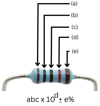
The resistor color code is a system used to indicate the resistance value of a resistor by using a series of colored bands or stripes. Each color corresponds to a specific digit, and the combination of colors on a resistor helps to determine its resistance value and tolerance.
| Color | Name | a, b and c band Significant figures | Multiplier (d) | Tolerance (e-band) |
|---|---|---|---|---|
| Black | 0 | x 1 | ||
| Brown | 1 | x 10 | 1% | |
| Red | 2 | x 100 | 2% | |
| Orange | 3 | x 1K | 0.05% | |
| Yellow | 4 | x 10K | 0.02% | |
| Green | 5 | x 100K | 0.5% | |
| Blue | 6 | x 1M | 0.25% | |
| Violet | 7 | x 10M | 0.1% | |
| Grey | 8 | x 100M | 0.01% | |
| White | 9 | x 1G | ||
| Gold | x 0.1 | 5% | ||
| Silver | x 0.01 | 10% |
First Band (1st Significant Digit): This band represents the first significant digit of the resistance value.
Second Band (2nd Significant Digit): This band represents the second significant digit of the resistance value.
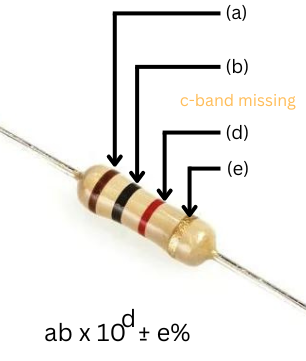
Third Band (3rd Significant Digit): This band represents the third significant digit of the resistance value. Sometimes, this band may not be present as shown in Fig 2.
Fourth Band (Multiplier): This band indicates the multiplier by which you should multiply the two significant digits to get the resistance value. It tells you how many zeros to add to the significant digits.
Fifth Band (Tolerance): This band indicates the tolerance or accuracy of the resistor's value. It shows the range within which the actual resistance might fall.
IEC labeling of fixed resistors
For compactness, the decimal is indicated using the symbol R, and 1000 is shown as a capital K. The use of a letter instead of a decimal point solves a printing problem – the decimal point in a number may not always be printed clearly, and the symbol R makes it clear that it is a resistor, not a capacitor/inductor.
| Resistor Value | IEC labelling |
|---|---|
| 0.1 Ohm | 0R1 |
| 1 Ohm | 1R0 |
| 33 Ohm | 33R |
| 3.3 kOhm | 3k3 |
| 10k | 10k |
| 100 kOhm | 100K |
| 4.7 MOhm | 4M7 |
E-series resistors
The E-series are classified by tolerance, and the E-series numbers represent the resistor numbers in each decade, i.e., E24 has 24 resistors in each decade.
| E-series | Tolerance | Number of values per decade |
|---|---|---|
| E3 | 0R1 | 3 |
| E6 | 1R0 | 6 |
| E12 | 33R | 12 |
| E24 | 3k3 | 24 |
| E48 | 10k | 48 |
| E96 | 100K | 96 |
| E192 | 4M7 | 192 |
Tolerance of a resistor
The tolerance of a resistor refers to the allowable variation or deviation in its resistance value from the specified or nominal resistance. It is usually expressed as a percentage. It indicates the range within which the actual resistance of the resistor may fall compared to its labeled resistance value. Common tolerance values for resistors include ±0.1%, ±0.5%, ±1%, ±2%, ±5%, ±10%, and ±20%. Lower tolerance values are used in precision instrumentation or high-accuracy circuits or where accurate value of resistor matters a lot. Higher tolerance resistors are inexpensive while lower tolerance are costly, so a careful selection of tolerance helps obtaining high performance with optimal cost.
Example : Upper and lower limits of 100 Ohm resistor
For example, if you have a resistor with a nominal value of 100 ohms and a tolerance of ±5%, this means that the actual resistance of the resistor can be anywhere between 5% higher or 5% lower than 100 ohms. Here's how it is calculated:
Upper Limit = Nominal Resistance + (Tolerance Percentage * Nominal Resistance)
Upper Limit = 100 ohms + (5% * 100 ohms) = 105 ohms
Lower Limit = Nominal Resistance - (Tolerance Percentage * Nominal Resistance)
Lower Limit = 100 ohms - (5% * 100 ohms) = 95 ohms
So, for a resistor with a ±5% tolerance, its actual resistance can be anywhere from 95 ohms to 105 ohms.
Power rating of a resistor
The power rating of a resistor, also known as its wattage rating, is a specification that indicates the maximum amount of electrical power (in watts) that the resistor can safely dissipate as heat without being damaged or experiencing a significant change in its electrical characteristics. Power rating is a critical parameter because it determines the resistor's ability to handle the heat generated when current flows through it. Exceeding the power rating can lead to overheating, which can result in resistor failure or a shift in its resistance value.
The power rating of a resistor is typically printed on its body or in the datasheet from the manufacturer/distributor and is expressed in watts. It's important to choose a resistor with a power rating that exceeds or at least matches the expected power dissipation in your circuit. To calculate power dissipation in a resistor, the formula is :
Power (P) = Current (I) × Voltage (V) or I2 × R
Resistors come in various power ratings, ranging from a fraction of a watt (e.g., 1/8 watt or 1/4 watt) for small signal applications to several watts or more for high-power applications. It's important to choose the \right resistor wattage rating to prevent overheating and maintain the resistor's reliability in your circuit.
Example of power dissipation through a 100 Ohms resistor
For example, if you have a resistor with a resistance of 100 ohms (R) and a current of 0.1 amperes (I) passing through it, the power dissipated in the resistor:
Power (P) = I2R = 0.12 × 100 = 1 watt
In this example, the power dissipation in the resistor is 1 watt. Therefore, a resistor with a power rating greater than 1 watt should be selected to ensure it can handle the heat generated at that power level without burning.
Voltage rating
Resistors typically do not have a specified voltage rating like other electronic components such as capacitors or diodes. Instead, the voltage across a resistor is determined by the circuit in which it is used and the power rating of the resistor. However, if the size/area of the resistor is too small (in orders of µm as in integrated circuits), dielectric breakdown can happen.
Temperature coefficient
The temperature coefficient of resistors, often referred to as the Temperature Coefficient of Resistance (TCR) or "alpha" (α), quantifies how the resistance of a resistor changes with temperature. It is typically expressed in units of ohms per degree Celsius (Ω/°C) or as parts per million per degree Celsius (ppm/°C).
$$R_t=R_o(1+\alpha{}(T-T_o))$$
There are two primary types of TCR for resistors:
Positive Temperature Coefficient (PTC): In resistors with a positive TCR, the resistance increases as the temperature rises. Common resistor materials with a positive TCR include most metals like copper and aluminum. For example, if a resistor has a TCR of +100 ppm/°C, its resistance will increase by 100 parts per million for every degree Celsius increase in temperature.
Negative Temperature Coefficient (NTC): In resistors with a negative TCR, the resistance decreases as the temperature rises. This type of resistor is often used in temperature-sensing applications. An example is the NTC thermistor, which has a highly negative TCR, meaning its resistance decreases significantly as temperature rises.
The TCR is an important consideration when selecting resistors for electronic circuits, especially in applications where precise resistance values are required over a wide temperature range. In precision electronics, you may prefer resistors with low TCR values to minimize the effect of temperature variations on circuit performance.
For example, some common TCR values for resistors are:
Carbon Film Resistors: These often have TCR values in the range of ±100 ppm/°C to ±500 ppm/°C, making them suitable for many general-purpose applications.
Metal Film Resistors: Metal film resistors typically have lower TCR values, ranging from ±10 ppm/°C to ±100 ppm/°C, making them more suitable for precision and temperature-sensitive applications.
Wirewound Resistors: Wirewound resistors can have very low TCR values, often in the range of ±5 ppm/°C to ±25 ppm/°C, and are used in high-precision applications where temperature stability is critical.