Resistors
A resistor is a passive two-terminal electronic component that is designed to restrict or limit the flow of electric current in a circuit when a voltage difference is applied across it. It does this by providing electrical resistance to the flow of electrons. Materials with high resistance, like rubber or wood, do not allow electricity to flow easily, while materials with low resistance, like copper or silver, allow electricity to flow without any impedance.
The current is proportional to the voltage across the terminal ends. This relation is represented by Ohm’s law:
$$R=\cfrac{V}{I}$$
Unit of resistance
The resistance is measured in ohms (Ω). An ohm is the resistance that occurs when a current of one ampere (A) passes through a resistor with a one-volt (V) drop across its terminals.
Symbol of resistor

The symbol for a resistor in an electrical or electronic circuit diagram is typically represented as a simple rectangular shape (IEC standard) or zig-zag line (ANSI standard) with two terminals, one at each end.
Series and parallel combination of resistors
Resistors in series

When resistors are connected in series, they are connected end-to-end, one after the other, forming a single pathway for current to flow. The total resistance Rtotal in a series combination is the sum of the individual resistances:
$$R_{total}=R_1+R_2+R_3+\dots{}$$
Resistors in parallel

When resistors are connected in parallel, they have the same voltage applied across their terminals, but they provide multiple paths for current to flow. The total resistance Rtotal in a parallel combination is the reciprocal of the sum of the reciprocals of the individual resistances:
$$\cfrac{1}{R_{total}}=\cfrac{1}{R_1}+\cfrac{1}{R_2}+\cfrac{1}{R_3}+\dots{}$$
To know more about series and parallel combination, please visit this page: Series and parallel combination of resistors.
Resistor power ratings

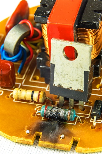
The resistor dissipates heat when a current is passed through it. Real resistors show an increase in temperature. This increase in temperature is dependent on the power rating of the resistor. Excessive increase in temperature changes the resistance or worse, may catastrophically destroy the resistor. The power rating of a resistor is measured in watts, and it's usually somewhere between ⅛W (0.125W) and 1W. A resistor should be used well under its power ratings for reliable operation and longevity.
The power across a resistor can be measured using the following formula:
If the current through the resistor is known,
$$P=I^2R$$
If voltage across it is known,
$$P=\cfrac{V^2}{R}$$
Resistor Noise
The major contributor to noise in a resistor is thermal noise caused by the random fluctuation of electrons in the resistive material. It is generally modeled as white noise (i.e. a constant RMS voltage over the frequency) and is given by the equation :
$$V_{noise}=\sqrt{4kTR\Delta{}f}$$
where Vnoise is the RMS noise voltage, R is the resistance value, k is Boltzmann’s constant, T is the temperature and Δf is the bandwidth of the system. It is possible to lower the noise by reducing the resistance, the operating temperature, or the system’s bandwidth.
Applications of resistor
Resistors are widely used in electronics and electrical circuits for various purposes, including:
- Voltage Division - The intermediate node of series resistors is used to create voltages other than supply voltages.
- Current Limiting - Resistors are used to limit the amount of current that flows in a circuit element. This is a useful safety function in many circuits e.g. limiting the current that can flow into an LED to manage its brightness and avoid permanent damage due to heating.
- Signal processing in opamp - Most op-amp circuits need to have their gain and feedback set by resistors.
- Pull-Up and Pull-Down Resistors - This functionality helps to reduce noise issues on high-speed data lines. When a data bus tri-states it is often necessary to pull it into a known state which should be above the switching threshold of other logic elements on the bus. Resistors are often used as weak pullups/pulldowns.
- Current Sensing - To measure current through a branch it is much easier to measure voltage, so inserting a resistor into the circuit to create a voltage drop is a common technique for measuring current.
Learn more about how to decide which type of resistor to use in a circuit - Resistor specifications
Types of resistors
Fixed resistors have a constant resistance value and are the most common type. Among them, carbon composition resistors are made from a mixture of carbon and binder, offering high energy tolerance but lower precision. Carbon film and metal film resistors are more stable, with metal film types providing better accuracy and lower noise. Wire-wound resistors, made by winding a resistive wire on a ceramic core, are used in high-power applications due to their excellent heat dissipation.
Variable resistors, such as potentiometers and rheostats, allow manual adjustment of resistance and are often used for volume controls or tuning circuits.
Surface mount resistors (SMD) are compact versions designed for automated circuit assembly.
Thermistors and photoresistors are examples of special resistors whose resistance varies with temperature and light, respectively, making them useful in sensing applications. Metal oxide resistors are preferred in high-voltage circuits due to their high stability and heat resistance.