Sallen-Key filters
The Sallen–Key topology is used to implement second-order active filters that easily enhance the Q of the filter using controlled positive feedback. The topology is more simple in comparison to other active filter topologies. In 1955, R. P. Sallen and E. L. Key described these filter circuits, and hence they are generally known as Sallen-Key filters. In a passive filters, the maximum Q achievable is 1/2. To obtain higher Q, active filters are required. Sallen-Key topology is on of such active filters topologyj.
While Sallen-Key might be more beneficial in terms of component count and ease of use, Multiple-Feedback (MFB) Filters are better in terms of distortion and stability.
Sallen-Key low pass filter circuit
Sallen-Key filters achieves higher Q by using a positive feedback. If the positive feedback is controlled, and localized to the cut-off frequency of the filter, almost any Q can be realized. Obtaining higher Q is limited mainly by the component tolerances and opamps gain-bandwidth product. The filter cutoff frequency should be much less than opamps's gain-bandwidth product. Figure 2 shows an opamp in non-inverting gain used in this manner. Capacitor C1, which is not connected to the ground, provides a positive feedback path.


 If R1=R2=R and C1=C2=C, the Q factor is :
From the above equation, it can be concluded that Q > 1/2 can be achieved if Gain (G) > 1, which is higher than any passive filter.
Moreover, setting G >= 3 makes the system unstable, as it causes at least one pole to move into the right half of the s-plane. This leads to either sustained oscillations or exponential growth of the output amplitude.

Intuitively, we can understand the operation in the following steps:
- At low frequencies, where C1 and C2 appear as open circuits, the system behaves as an opamp in a non-inverting configuration providing a gain of G (=1+Rf/Rg).
- At high frequencies, where C1 and C2 appear as short circuits, the signal is attenuated at the amplifier’s input, the amplifier amplifies this input to its output, and the signal does not appear at Vo.
- Near the cut-off frequency, if gain G is set close to but less than 3 (e.g., 2.5), Vo becomes very high which is basically feeding current through C1 from Vo to vx. This increases the input at the non-inverting pin (vy) resulting in high Q of this filter.
Sallen-Key high pass filter circuit
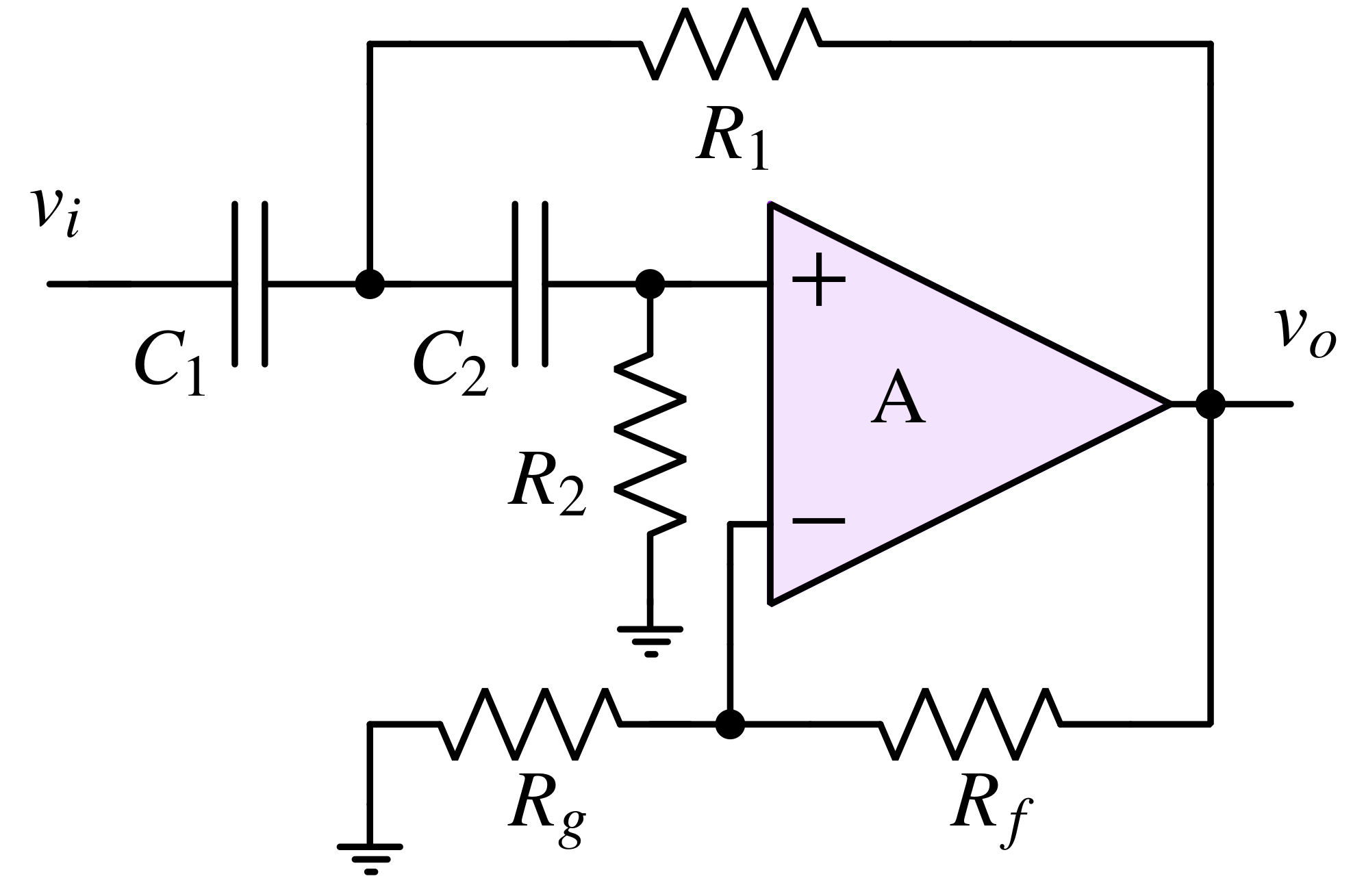
Sallen-Key high pass filter is shown in above figure. Instead of R1 connected to the ground, it is connected to the output of the amplifier to provide positive feedback. Intuitively, we can understand the operation in the following steps:
- At low frequencies, where C1 and C2 appear as open circuits, R2 is pulling down the non-inverting node to the ground. This means no signal is getting amplified.
- At high frequencies, where C1 and C2 appear as short circuits, vi completely appears at the non-inverting pin of the opamp because the impedance of C2 is lower than R2.
- Near the cut-off frequency, similar to the Sallen-Key low pass filter, a current is injected through R1 into C2 from the Vo node. This leads to higher signal strength at the non-inverting pin which results in higher Q.
Transfer function of a Sallen-Key high-pass filter
$$\cfrac{V_o(s)}{V_i(s)}=\cfrac{s^2R_1R_2C_1C_2G}{1+s{(1-G)R_2C_2+R_1C_2+C_1R_1}+s^2R_1R_2C_1C_2}$$
Cutoff frequency : $$\omega{}_o=\cfrac{1}{\sqrt{R_1R_2C_1C_2}}$$
Quality factor : $$\cfrac{\sqrt{R_1R_2C_1C_2}}{(1-G)R_2C_2+R_1C_2+R_1C_1}$$
Where G:
$$G=1+\cfrac{R_f}{R_g}$$
Sallen-Key bandpass filter circuit
Transfer function of a Sallen-Key band-pass filter
$$\cfrac{V_o(s)}{V_i(s)}=\cfrac{GsC_2R_2/(1+R_1/R_2)}{1+sC_2R_2\left(1+\cfrac{R_1}{R_3}-(G-1)\cfrac{R_1}{R_2}\right)+\cfrac{s^2C_1C_2R_1R_2}{\left(1+\cfrac{R_1}{R_2}\right)}}$$ Where, $$G=1+\cfrac{R_f}{R_g}$$
Center Frequency: $$\omega{}_o=\cfrac{\sqrt{1+\cfrac{R_1}{R_2}}}{\sqrt{C_1C_2R_1R_2}}$$
Quality factor: $$Q=\cfrac{\sqrt{C_1C_2R_1R_2}}{R_2C_2\sqrt{1+\cfrac{R_1}{R_2}}\left(1+\cfrac{R_1}{R_3}-(G-1)\cfrac{R_1}{R_2}\right)}$$
Generalized Sallen-Key filter
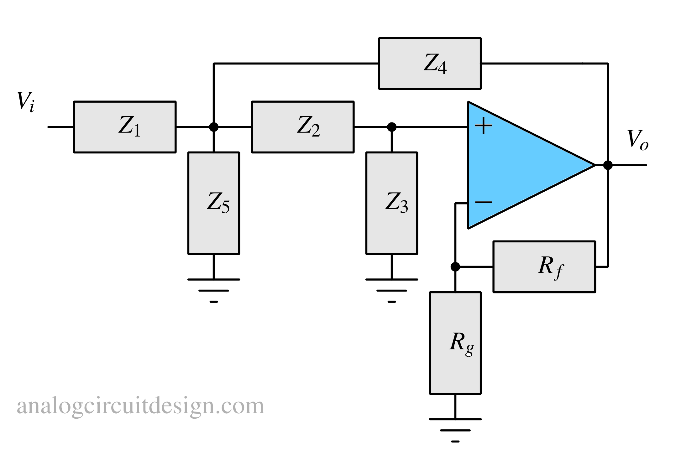
The circuit illustrated above represents a generalized version of the Sallen-Key configuration1, where the passive filter elements are expressed as generalized impedances (Z), and the resistors Rf and Rg determine the passband gain.
Derivation
KCL at note Vf: $$V_f\left(\cfrac{1}{Z_1}+\cfrac{1}{Z_2}+\cfrac{1}{Z_4}+\cfrac{1}{Z_5}\right)=V_i\left(\cfrac{1}{Z_1}\right)+V_p\left(\cfrac{1}{Z_2}\right)+V_o\left(\cfrac{1}{Z_4}\right)$$ KCL at note Vp: $$V_p\left(\cfrac{1}{Z_2}+\cfrac{1}{Z_3}\right)=V_f\left(\cfrac{1}{Z_2}\right)$$ $$V_f=V_p\left(1+\cfrac{Z_2}{Z_3}\right)$$ KCL at node Vn: $$V_n\left(\cfrac{1}{R_3}+\cfrac{1}{R_4}\right)=V_o\left(\cfrac{1}{R_4}\right)$$ $$V_n=V_o\left(\cfrac{R_3}{R_3+R_4}\right)$$ Using the virtual short property of opamp : $$V_p=V_n$$ Using above relations, we get : $$\cfrac{V_o}{V_i}=\cfrac{1}{Z_1}\left(\cfrac{1}{\cfrac{1}{K}\left(1+\cfrac{Z_2}{Z_3}\right)\left(\cfrac{1}{Z_1}+\cfrac{1}{Z_2}+\cfrac{1}{Z_4}+\cfrac{1}{Z_5}\right)-\cfrac{1}{Z_2K}-\cfrac{1}{Z_4}}\right)$$ Where K: $$K=1+\cfrac{R_f}{R_g}$$
$$\cfrac{V_o}{V_i}=\cfrac{1}{Z_1}\left(\cfrac{1}{\cfrac{1}{K}\left(1+\cfrac{Z_2}{Z_3}\right)\left(\cfrac{1}{Z_1}+\cfrac{1}{Z_2}+\cfrac{1}{Z_4}+\cfrac{1}{Z_5}\right)-\cfrac{1}{Z_2K}-\cfrac{1}{Z_4}}\right)$$ Where K: $$K=1+\cfrac{R_f}{R_g}$$
We can create any type of Sallen-Key filter using the values mentioned in the table below :
| Low pass | High pass | Band pass | |
|---|---|---|---|
| $$Z_1$$ | $$R_1$$ | $$\cfrac{1}{sC_1}$$ | $$R_1$$ |
| $$Z_2$$ | $$R_2$$ | $$\cfrac{1}{sC_2}$$ | $$\cfrac{1}{sC_2}$$ |
| $$Z_3$$ | $$\cfrac{1}{sC_1}$$ | $$R_2$$ | $$R_3$$ |
| $$Z_4$$ | $$\cfrac{1}{sC_2}$$ | $$R_1$$ | $$R_2$$ |
| $$Z_5$$ | $$\infty{}$$ | $$\infty{}$$ | $$\cfrac{1}{sC_1}$$ |
Sallen Key vs Multi-Feedback Filter
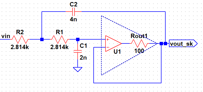
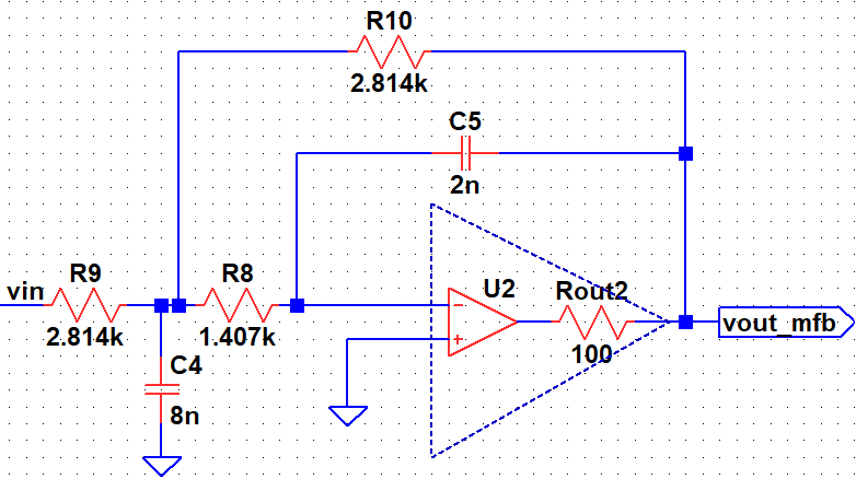
In the AC response of Sallen Key low pass filter, the gain starts increasing after certain frequency due to finite output impedance of the operational amplifier2. This is not desired. However, if we observe the multi-feedback filter's response, the gain continue decreasing with frequency which is desired. However, the rate of decrease has reduced.
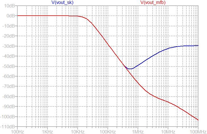
As shown above, the output of the Sallen-Key starts rising beyond 500kHz (shown in blue color). In contrast, the output of the multi-feedback filter continue dropping which is desirable.
The output AC response of Sallen-Key is increasing because of the finite output impedance of the operational amplifier. At high frequency, when opamp's gain fall, capacitor C2 provides a feedforward path to the output. Since, the output is grounded by the output impedance (which is high at high frequency), the feedforward path starts dominating as shown above.
In Multi-feedback amplifier, even though it has identical opamp with finite output impedance, it does not have this problem. At high frequency, C4 shorts the input signal to ground before any signal goes through the possible feedforward path formed by C5.
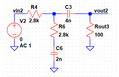
The equivalent model which explains the high frequency behaviour of the Sallen Key is shown. C6 represents C1, R6 represents R1, C3 represent C2, R4 represents R2.
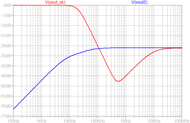
At high frequency, the response merges indicating operational-amplifier's non-zero output impedance and finite gain-bandwidth product.