Star Delta Connection
In 3-phase electrical systems, Star (Y) and Delta (Δ) are the two primary methods used to connect the windings of generators, transformers, and motors. Each configuration offers different characteristics for voltage, current, and power handling.
Polyphase systems and 3-phase systems
A single-phase AC power system consists of a power source connected to a load through a pair of wires. There are circuits and systems where the AC power source operates at the same frequency and magnitude of voltage but in different phases, known as polyphase systems. The most common polyphase systems are 3-phase systems, where three power sources have the same frequency and amplitude but a phase difference 120°. This is particularly 120° because the armature coils in the generator are placed 120° apart.
Star to Delta & Delta to Star Conversion Calculator
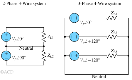
The three-phase systems can be wired in two ways:
Star connection
In a Star Connection, the three-phase wires converge at a central po\int known as the star or common po\int, also called Neutral po\int (N). When solely the three-phase wires are employed, it's referred to as a 3 Phase 3 Wire system. However, if the Neutral po\int is also utilized, which is commonly the case, it becomes a 3 Phase 4 Wire system.
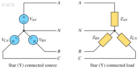
Star, Wye (Y) and T-network
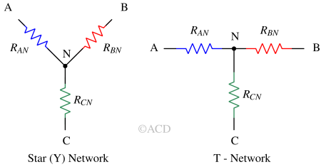
This connection resembles the shape of the letter "Y" (hence the name Wye) or the letter "T" (Tee). If terminal C is connected to a common voltage (e.g., ground) then a star network can be converted into 2-port network.
Delta connection
In a Delta Connection, a three-phase electrical setup comprises three elements arranged in a triangular configuration. This connection is alternatively termed a mesh connection. Delta configuration specifically incorporates solely three phase wires without the utilization of a neutral wire.
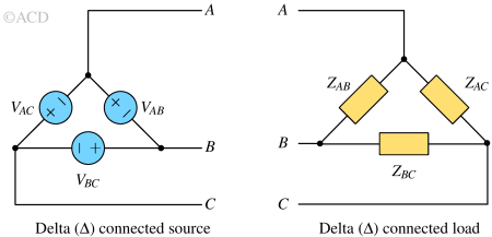
Delta (Δ) and Pi (π) network

Pi-network is same as Delta network. If we look carefully, Pi-network is equivalent to inverted delta. The terminal "C" is taken and grounded to convert it from 3 terminal Delta (Δ) network into two terminal Pi (π) - network. It is also called mesh connection.
Line voltage-currents and Phase voltage-currents
- Line current (IL) : It represents the current that moves from the generator to the load through each transmission line within a three-phase system.
- Line voltage (VL) : It refers to the voltage across each line pair (line to line), not including the neutral line if it is present.
- Phase current (IP) : It represents the current that passes through each phase within a three-phase load.
- Phase voltage (VP): It denotes the voltage specific to each phase.
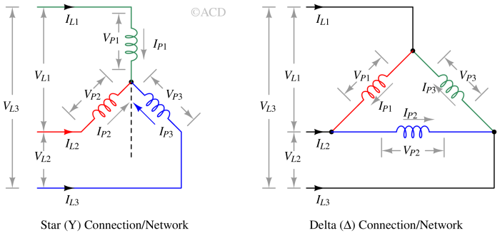
VP1, VP2, VP3 are the phase voltages. VL1, VL2, VL3 are the line voltages. IP1, IP2, IP3 are the phase currents. IL1, IL2, IL3 are the line currents. Please note that for a star network, the phase current and line currents are the same. For a delta network, the phase voltage and line voltage are same.
Comparison between star and delta connection
A table of comparison is mentioned below:
Table 1 : Comparison and difference between star and delta connection | Difference | Star Connection | Delta Connection | | --- | --- | --- | | Connection | In a STAR Connection, three coils have their corresponding ends (similar ends) connected to create a neutral po\int resembling the letter “Y”. From this neutral po\int, a shared wire is extracted, referred to as the Neutral Wire. | In a DELTA Connection, the opposite ends of three coils are linked, shaping the configuration akin to the Greek alphabet "Δ". Put differently, the end of each coil is linked to the starting po\int of another coil, forming the connections for the three-phase wires. | | Neutral po\int | A po\int known as the Neutral or Star Po\int exists. | Delta Connection does not include a Neutral Po\int. | | Number of conductors | The star connection comprises four conductors, consisting of line wires along with one neutral wire. | The delta connection consists of only three conductors (line wires) | | Line and phase current for balanced circuit | Line current = Phase current | Line current = √3 X Phase current | | Line and phase voltage | Line voltage = √3 X Phase voltage | Line voltage = Phase voltage | | Speed of a motor | Assuming phase load is same in both star or delta connection. For same line voltage, the phase voltage is √3 times lesser. So, motor speed is less. | Assuming phase load is same in both star or delta connection. For same line voltage, the phase voltage is equal to line voltage. So, motor speed is higher. | | Usage | Generator | Motor | | Preference | The star connection is frequently employed in appliances requiring a lower starting current because phase current is lower than delta connection, typically for small-load applications. | The delta connection finds common use in high starting torque applications because phase current is higher than star connection, such as powering large electric motors utilized in various industrial settings. |
Applications of Star and Delta connections
- The star connection is used in the generator side for long distance transmission of electric power. where resistive losses (I2R) should be minimal. This is due to the fact that the star connection gives a line voltage that is √3 greater than the delta connection. Hence for the same power, line current is √3 times smaller.
- Delta connection are not desirable in long distance transmission because of possibility of circulating current.
- Three phase power is used in industrial wiring where large power is required.
Delta to Star transformation
In this section we will learn to transform a Delta network into a Star network :
Delta to star transformation derivation
If a Delta network is given, we have the values of RAC, RBC and RAB. We need to find the values of RAN, RBN and RCN of the Star network in terms of RAC, RBC and RAB.
If we measure the value of resistance between terminal A and C of star network, it should be equal to the resistance offered by terminal A and C of Delta network. Terminal B is open.
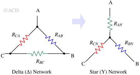
$$R_{AN}+R_{CN}=R_{CA}||(R_{AB}+R_{BC})hspace{0.5in}\text{-- Eq. 1}$$
$$\implies{}R_{AN}+R_{CN}=\cfrac{R_{CA}R_{AB}+R_{CA}R_{BC}}{R_{CA}+R_{BC}+R_{AB}}hspace{0.5in}\text{-- Eq. 2}$$
Similarly,
$$R_{AN}+R_{BN}=R_{AB}||(R_{AC}+R_{BC})hspace{0.5in}\text{-- Eq. 3}$$
$$\implies{}R_{AN}+R_{BN}=\cfrac{R_{AB}R_{AC}+R_{AB}R_{BC}}{R_{CA}+R_{BC}+R_{AB}}hspace{0.5in}\text{-- Eq. 4}$$
and,
$$R_{CN}+R_{BN}=R_{BC}||(R_{AB}+R_{CA})hspace{0.5in}\text{-- Eq. 5}$$
$$\implies{}R_{CN}+R_{BN}=\cfrac{R_{BC}R_{AB}+R_{BC}R_{CA}}{R_{CA}+R_{BC}+R_{AB}}hspace{0.5in}\text{-- Eq. 6}$$
Subtracting Equation 2 from Equation 4, we get :
$$R_{CN}-R_{BN}=\cfrac{R_{CA}R_{BC}-R_{AB}R_{BC}}{R_{CA}+R_{BC}+R_{AB}}hspace{0.5in}\text{-- Eq. 7}$$
Now adding Equation 6 and Equation 7 :
$$2times{}R_{CN}=\cfrac{2times{}R_{CA}R_{BC}}{R_{CA}+R_{BC}+R_{AB}}hspace{0.5in}\text{-- Eq. 8}$$
$$\implies{}R_{CN}=\cfrac{R_{CA}R_{BC}}{R_{CA}+R_{BC}+R_{AB}}hspace{0.5in}\text{-- Eq. 9}$$
Similarly we can obtain relationship of RAN, RBN. The final results are listed in next section.
Delta to Star transformation formula
To convert a Delta network into a Star network, we have following relationships:
$$R_{AN}=\cfrac{R_{AB}R_{CA}}{R_{AB}+R_{CA}+R_{BC}}hspace{0.5in}\text{-- Eq. 10}$$
$$R_{BN}=\cfrac{R_{BC}R_{AB}}{R_{AB}+R_{CA}+R_{BC}}hspace{0.5in}\text{-- Eq. 11}$$
$$R_{CN}=\cfrac{R_{BC}R_{CA}}{R_{AB}+R_{CA}+R_{BC}}hspace{0.5in}\text{-- Eq. 12}$$
Delta to Star transformation calculator
Utilize the following Delta to Star Conversion Calculator to transform any Delta resistance network into a Star configuration by inputting the corresponding resistances for each node in the Delta network.
| Delta | RCA | RAB | RBC |
|---|---|---|---|
| Star | RAN\= | RBN\= | RCN\= |
Star to Delta transformation
In this section we will learn to transform a star network into a delta network. This technique help us simplify complex circuits and get more insights.
Star to Delta transformation derivation
Star-to-delta conversion, also known as the "Y-to-Δ" transformation, is a technique to convert a resistive circuit from a star (Y) configuration to a delta (Δ) configuration, or vice versa.
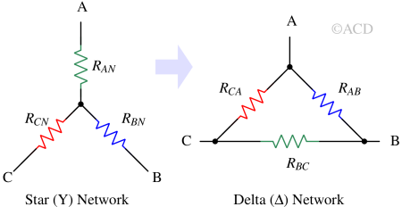
If a star network is given, we have the values of RAN, RBN and RCN. We need to find the values of RCA, RBC and RAB of the Delta network. So, we need to find the RCA in terms of RAN, RBN and RCN.
We can reuse the result of Delta to Star transformation.
Dividing Equation 10 by Equation 11, we obtain :
$$\cfrac{R_{AN}}{R_{BN}}=\cfrac{R_{CA}}{R_{BC}}hspace{0.25in}\text{-- Eq. 13}$$
$$\implies{}R_{BC}=\cfrac{R_{BN}}{R_{AN}}R_{AC}hspace{0.25in}\text{-- Eq. 14}$$
Similarly, dividing Equation 11 by Equation 12 :
$$\cfrac{R_{BN}}{R_{CN}}=\cfrac{R_{AB}}{R_{AC}}hspace{0.25in}\text{-- Eq. 15}$$
$$\implies{}R_{AB}=\cfrac{R_{BN}}{R_{CN}}R_{AC}hspace{0.25in}\text{-- Eq. 16}$$
Substituting Equation 14 and 16 into Equation 11.
$$R_{BN}=\cfrac{R_{AC}R_{BN}^2/(R_{AN}R_{CN})}{1+R_{BN}/R_{AN}+R_{BN}/R_{CN}}hspace{0.25in}\text{-- Eq. 17}$$
$$\implies{}R_{AC}=\cfrac{R_{AN}R_{CN}+R_{BN}R_{CN}+R_{AN}R_{BN}}{R_{BN}}hspace{0.25in}\text{-- Eq. 18}$$
Similarly we can obtain relationship of RAB, RBC. The final results are listed in next section.
Star to Delta transformation formula
$$R_{CA}=\cfrac{R_{AN}R_{CN}+R_{AN}R_{BN}+R_{BN}R_{CN}}{R_{BN}}$$
$$R_{AB}=\cfrac{R_{AN}R_{CN}+R_{AN}R_{BN}+R_{BN}R_{CN}}{R_{CN}}$$
$$R_{BC}=\cfrac{R_{AN}R_{CN}+R_{AN}R_{BN}+R_{BN}R_{CN}}{R_{AN}}$$
Star to Delta transformation calculator
Utilize the following Star (Wye) to Delta Conversion Calculator to transform any star resistance network into a delta configuration by inputting the corresponding resistances for each node in the star network.
| Star | RAN | RBN | RCN |
|---|---|---|---|
| Delta | RCA\= | RAB\= | RBC\= |