Summing amplifier or Voltage adder
The summing amplifier topology is used to add voltages linearly. It uses opamp in inverting gain configuration to add the currents from different branches. Those currents are passed through a resistor to create voltage. This is a very common topology used in filter design and data converters to add signals linearly.
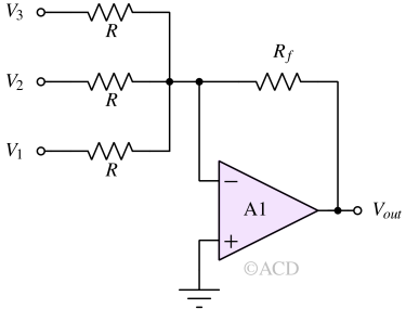
The output and input voltages are related by :
$$V_{out}=-\cfrac{R_f}{R}\left(V_1+V_2+V_3+\cdots{}\right)$$
Op Amp adder circuit diagram
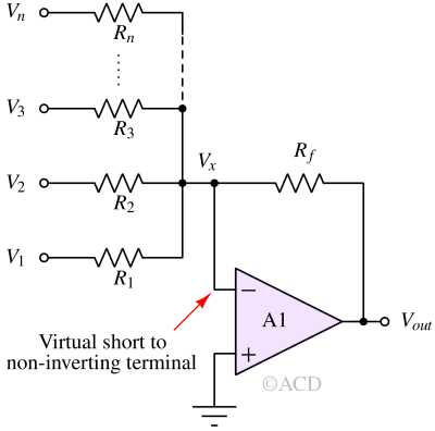
It is an extension of inverting amplifier topology. In an inverting amplifier, there is only one input. In a voltage adder (Op Amp adder), there are multiple inputs. Please note that the node Vm (inverting terminal of the op-amp) is virtually shorted to zero (non-inverting terminal of the op-amp). So, the current injected into the virtual short terminal due to each input voltage is (vi / R). All these currents will flow through resistor Rf. These currents cannot go into the inverting terminal because of the infinite input impedance of the op-amp.
Op amp adder formula
The current going into the virtual terminal due to voltage V1 :
$$i_1=\cfrac{V_1}{R_1}$$
similarly due to V2, V3 and Vn :
$$i_2=\cfrac{V_2}{R_2}$$
$$i_3=\cfrac{V_3}{R_3}$$
$$i_n=\cfrac{V_n}{R_n}$$
all the currents will get added up to form if, and flow through Rf to produce output voltage :
$$V_{out}=-R_f\cdot{}i_f$$
According to the ideal properties of the opamp, the inverting terminal is virtually shorted to the non-inverting terminal. The non-inverting terminal's potential is zero, so the inverting terminal's node potential is also zero. Also, the current going inside the inverting and non-inverting terminal is zero. So, the entire current if will flow through Rf. So, the final output voltage formula for voltage adder using opamp is :
$$V_{out}=-R_f\left(\cfrac{V_1}{R_1}+\cfrac{V_2}{R_2}+\cfrac{V_3}{R_3}+\cdots{}\right)$$
Non-inverting summing amplifier
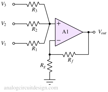
Non-inverting summing amplifier adds the voltage at the non-inverting terminal of the op-amp. At this node, the voltage is inversely proportional to the resistance seen from the node to the voltage source.
The voltage at the non-inverting terminal of the op-amp is :
$$V_{p}=\cfrac{V_3R_2R_1+V_2R_3R_1+V_1R_3R_2}{R_1R_2+R_2R_3+R_3R_1}$$
So, the output voltage is (following the observations in non-inverting op amp):
$$V_{out}=\left(1+\cfrac{R_f}{R_g}\right)V_p$$
To make things simple, if we assume that R1 = R2 = R3 = R, we get :
$$V_{p}=\cfrac{V_1+V_2+V_3}{3}$$
So, a simpler version of the output voltage of non-inverting op amp adder is :
$$V_{out}=\left(1+\cfrac{R_f}{R_g}\right)\left(\cfrac{V_1+V_2+V_3}{3}\right)$$
Applications
Op-amp adder has a lot of applications. Some most popular applications are mentioned below:
Signal processing
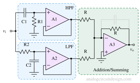
In signal processing, it is very convenient to use an op-amp adder for two or more signals. For example, a bandstop filter can be made using adding a low pass filter and a high pass filter. As shown in the above figure, op-amp A1 forms an active high pass filter, op-amp A2 forms an active low pass filter. Op-amp A3 forms the adder.
Binary digital to analog converters
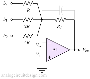
Weights can be added to each voltage source in the form of resistors. In this way, some voltage sources greatly influence the output voltage while some have a small influence on the output voltage. The most significant bit can be made using a small resistor while the least significant bit can be made using the highest resistor. To form a binary DAC, the resistors should be of the power of 2.
Audio mixers
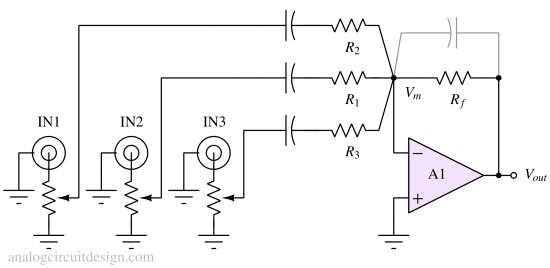
This is an electronic device used for mixing, balancing, and combining different sounds and audio signals, sources like microphones, instruments, and synthesizers, or previously recorded audio.
Multiplying DAC (M-DAC)
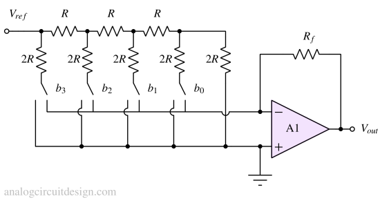
In a multiplying DAC (as shown above in Fig), there are N-branches for N-bit DAC. Each branch is providing binary weighted current which can either be steered into the virtual short of the op-amp or the ground. The binary weights are achieved using R-2R ladder. The currents at the virtual ground are added together to form the analog voltage.
Op Amp level shifter (Analog level shifter)
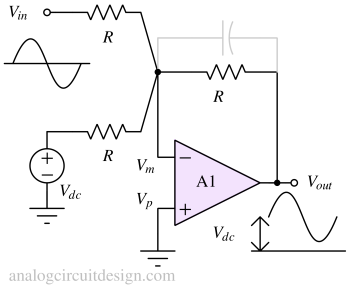
An analog level shifter can be made using op amp adder. Analog level shifter means that it can level shift the continuous waveform also. In contrast digital level shifter can level shift only 2 voltage levels. To do analog level shifting, a constant DC bias voltage is given at one of the inputs and the analog signal is given at another input. The output is addition of the DC and AC signal.