Precision rectifier (Super diode)
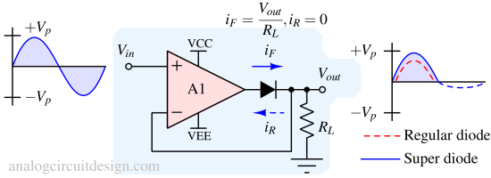
A regular diode has a voltage drop of near 0.7V across it. To eliminate this diode drop voltage, we use an opamp to create a "super-diode" which eliminates the 0.7V (dead-band) and fairly simple to use. It is also called a precision rectifier.
Circuit implementation of a simple super diode

When Vin is positive, due to the very high gain of the opamp A1, the output tries to go toward supply. The opamp forward biases the diode. Finally, the conducting diode closes the feedback loop such that Vout=Vin (virtual short). Please note that in a regular diode, this relation would have been Vout=Vin-0.7V.
When Vin is negative (less than inverting pin voltage), due to high gain, the output tries to go to the negative supply. For the output to go negative, the diode has to source reverse current. That means that the diode is reversed-biased and the opamp loop is open/broken. So, the opamp output eventually saturates to the negative supply rail. Vout remains as high-impedance terminal like a regular diode circuit.
The above circuit can also be categorized as a non-inverting precision rectifier.
Limitations of simple super diode based precision rectifier
Although the V-I characteristics of a super-diode are near ideal, there are certain limitations to a super-diode.
- Since the diode is connected in a series of the opamp, the current has to be supplied by the opamp itself. So, before using it for any power application, it is required to ensure that the opamp specification can supply that current.
- When the diode is forward-biased, the frequency of Vin should not be higher than the opamp's bandwidth.
- When the diode is reverse-biased by the opamp, the opamp is saturated. The opamp is saturated because there is no negative feedback regulation. It's in an open loop. The diode's reverse recovery time and opamp's overdrive recovery time limit the turn-on speed.
- The diode drop is absorbed by the opamp's output stage, so need to ensure that the opamp has sufficient headroom when Vin peaks.
Improved precision rectifier circuit

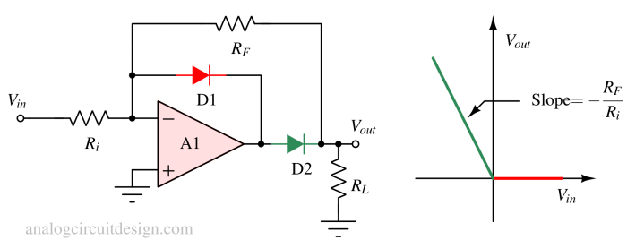
An improved alternative to the simple super diode is shown in Fig 2. In this circuit, the opamp does not go into saturation because, in the non-conducting phase, diode D1 turns on and clamps the output to -0.7V. Other limitations of opamps are still applicable like limited slew-rate and bandwidth.
- Conducting phase: When Vin is greater than zero, the opamp A1 tries to go towards the negative rail due to high gain. In that case, the diode D1 turns on and completes the feedback circuit with gain -RD1/Ri. This gain is very low (near zero) because the diode's resistance (RD1) is very low. D2 is reversed-biased because it has to supply a reverse current to support negative output to RL. When Vi > 0,
$$V_{out}=-\cfrac{R_{D1}}{R_i}\cfrac{R_L}{R_L+R_F}V_{in}$$
Since RD1 << Ri,
$$V_{out}\simeq{}0$$ - Non-conducting phase: When Vin is lesser than zero, the opamp A1 tries to go towards the positive rail due to high gain. In that case, the diode D2 turns on and completes the feedback circuit through D2 and RF with gain -RF/Ri. This gain is significant because RF is much larger than the diode's resistance (RD1). D1 is reversed-biased because the output voltage is at a higher potential than the inverting pin. When Vi < 0,
$$V_{out}=-\cfrac{R_{F}}{R_i}V_{in}$$
The circuit mentioned in Fig 2 can be categorized as an inverting precision rectifier. The circuit mentioned above is still a half-wave precision rectifier. Full wave precision rectifier is discussed next.
Precision full wave rectifier circuit
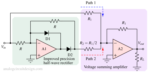
In the circuit shown in Fig 3, the full-wave precision rectifier is constructed using :

Working of a full-wave precision rectifier
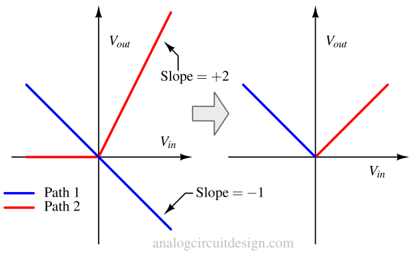
The circuit can be analyzed by separating it into two paths. Path-1 is always conductive with a gain of +1. The path is conducive only when Vin is negative. If R2 is not R1/2, the gain of the Path-2 is not -2 when it is conducting. If the gain had been kept -1 by keeping R2=R1, then the output (Vout) would be zero because it would cancel the Path-1 signal which is always active. To get the same gain when Vin is positive, the gain of Path-2 is kept -2 by keeping R2=R1/2.

In Fig 4, it is shown that the overall transfer function of the circuit mentioned in Fig 3 (precision full-wave rectifier) is like y=|x|.
Applications of precision rectifiers
-
Signal Conditioning and Measurement: Precision full-wave rectifiers are used in instrumentation and measurement systems to convert AC sensor signals (such as from temperature sensors, strain gauges, ultrasonic sensors, and ECG) into a clean and precise DC voltage for accurate measurements and data acquisition.
-
Audio Signal Processing: In high-quality audio equipment and amplifiers, precision full-wave rectifiers can be used to rectify audio signals, preserving the signal's fidelity while eliminating the negative half-cycle. This is useful in audio envelope detection and peak detection.
-
Waveform Reconstruction: In communication systems, precision full-wave rectifiers can be used for demodulating amplitude-modulated (AM) signals, helping to recover the original message signal from the carrier wave.
-
Power Metering and Energy Measurement: Precision rectifiers are used in power metering and energy measurement systems to convert AC voltage or current signals into DC values for accurate power measurement and billing.
-
Feedback Control Systems: In feedback control systems, precision full-wave rectifiers can be used to provide a DC representation of an AC signal for control and feedback purposes. For example, motor control circuits, help maintain precise control over the motor speed and direction.
-
Photodetectors and Light Measurement: Precision rectifiers are used with photodetectors (e.g., photodiodes) to convert the AC output of the photodetector into a DC signal for light intensity measurement and optical communication systems.
-
Test and Measurement Equipment: Precision full-wave rectifiers are commonly found in various test and measurement instruments, such as oscilloscopes, signal analyzers, and function generators, where amplitude (voltage-peak) measurement is required to control the gain of the signal acquisition system.
References
- Precision Full-Wave Rectifier : Texas Instruments