The Quartz crystal oscillator
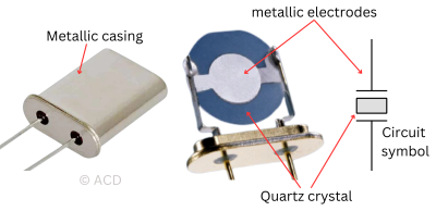
A crystal oscillator is used to create a stable clock signal. This means the frequency stays the same and does not drift with time. Also, the crystal oscillator's sensitivity to temperature, humidity, and other physical factors is minimal. Other alternatives to derive clock signals are RC and LC oscillators, which are sensitive to temperature and impact frequency. Crystal oscillators work on the principle of the Piezoelectric effect. Piezo means “to press” in Greek. The most common piezoelectric crystal is Quartz. Quartz is a crystalline form of silicon dioxide (SiO2).
Why are Quartz crystal oscillators the most popular?
Quartz is the most stable form of silicon dioxide on Earth, making it the most abundant. Silicon dioxide is ubiquitous due to the planet's high abundance of silicon and oxygen. Like many minerals, quartz is commonly found in rocks. Natural quartz isn’t used anymore; instead, synthetically grown quartz is used to have very tight control over frequency properties. Synthetic quartz is grown in an autoclave, a high-pressure, high-temperature container where the quartz bars grow chemically over several months.
What is XTAL?
XTAL is an informal abbreviation for crystal oscillators.
What is Piezoelectricity?
It is the ability of a material (in the case of the Quartz crystal) to generate an electric charge when subjected to pressure. Piezoelectric materials can turn mechanical stress into electricity and electricity into mechanical vibrations. This back-and-forth conversion of mechanical energy into electrical energy and vice versa manifests as resonance, like in LC oscillators in the pure electrical domain.
Difference between Piezoelectricity and Pyroelectricity
The terms piezoelectric and pyroelectric may seem confusing. They refer to different types of materials. The distinctions are outlined below:
| Piezoelectricity | Pyroelectricity |
|---|---|
| Electric charge generation in response to mechanical stress. | The release of electric charge due to temperature changes in a material. |
| Piezoelectric materials are used as pressure sensors | Pyroelectric materials are used as temperature sensors |
| Materials: Quartz, Barium Titanate, Lead Niobate, Lead Zirconate titanate, Zinc oxide (ZnO) | Examples: Semiconductors, Gallium nitride |
Types of Crystal oscillators
Quartz crystal oscillators come in two types: a plain quartz crystal and a complete oscillator package containing all necessary circuit components to output periodic waveforms directly. The differences are outlined below:
Quartz crystal (Passive oscillator)
It is also called quartz crystal. Because of its passive nature, it is less expensive. However, an additional circuit is required to generate oscillations, which the system designer must design using transistors. It adds additional development time and bill of materials (BOM).
Quartz crystal oscillator (Quartz crystal + transistors)
It has an additional built-in circuit to generate oscillations. The user connects the device to a rated power supply, and the device starts generating a square wave. It's more expensive than a quartz crystal. It is easy to use (plug and play) and lowers the bill of materials (BOM).
Quartz crystal (passive oscillator) specifications
- Frequency (kHz or MHz): The nominal frequency at which the crystal will oscillate if optimal circuit connections are made.
- Package: Traditionally, quartz-based devices were constructed with through-hole metal packages (e.g., HC49). However, with the advent of surface mount technology, these devices became smaller, and their construction shifted to ceramic-based packages.
- Frequency Tolerance (+-ppm): This indicates the frequency accuracy at room temperature. It is set during the crystal's manufacturing. For example, if a 16 MHz crystal oscillator claims to be 100ppm accurate, the frequency will lie between 16MHz +-1600Hz (between 15998400 Hz and 16001600 Hz).
- Frequency stability (+-ppm): Frequency stability indicates how the frequency changes with temperature, and the performance obtained varies with the cut angle of the quartz used.
- Operating temperature range: The operating temperature range is specified in conjunction with the frequency stability, as the two values are related. A quartz crystal specified at -40 to 85°C will still operate at broader temperature ranges but will not achieve the same frequency stability.
- Load capacitance: The load capacitance is the specific capacitance that the quartz crystal requires within the oscillator circuit to maintain optimal frequency accuracy at room temperature. If the load capacitance is incorrect, it will shift the frequency from its intended value and, in the worst case, cause the frequency to fall outside the acceptable tolerance range.
Quartz crystal oscillator (Active oscillator) specifications
- Frequency (kHz or MHz): The nominal frequency at which the crystal will oscillate if optimal circuit connections are made.
- Package: Modern active crystal oscillator comes with SMD package.
- Frequency Tolerance (+-ppm): Similar to a quartz crystal, it tells the maximum error it can have from a nominal frequency number at room temperature. It is more controlled in active oscillators because the manufacturer can control the load capacitance.
- Frequency stability (+-ppm): Frequency stability indicates how the frequency changes with temperature.
- Operating temperature range: Similar to a quartz crystal, it specifies the temperature for which the promised frequency stability is achievable.
- Load capacitance: There is no requirement for load capacitance in an active oscillator as the manufacturer takes care of it in the internal circuit.
- Output Type: HCMOS, Clip-sine, Sine, LVDS, LVPECL
- Supply Voltage: 1.8V, 3.3V, 3.0V, 5V
Types of controlled oscillators
Various controlled oscillators are used to achieve better frequency stability and aging. Some types of crystal oscillators based on how the frequency drift is controlled are tabulated below:
| Types of crystal oscillator | Frequency tolerance | Aging |
|---|---|---|
| Oven-controlled crystal oscillators (OCXO) | 0.1 ppm | 0.2 ppm/yr |
| Temperature-compensated oscillators (TCXO) | 2 ppm | 2 ppm/yr |
| Voltage controlled oscillators (VCXO) | 1000 ppm | 5 ppm/yr |
| Quartz crystal oscillators (XTAL) | 10 ppm | 5 ppm/yr |
Crystal oscillator circuit
A quartz crystal cannot produce oscillation on its own. It needs to be connected to an amplifier in a positive feedback manner to produce oscillations. The amplifier can be implemented using a transistor, op-amp, or digital gate. Op-amps are suitable for oscillators at low frequencies when excellent linearity is required. Gates are suitable for low to medium frequencies, and single transistors are ideal for any frequencies. A single transistor circuit is the only option for very high frequencies because single transistors offer the least parasitic capacitance.
In the following sections, let’s learn how to model a crystal in the electrical domain and create a functional oscillator circuit from a quartz crystal.
Crystal oscillator circuit model
The wire leads are connected to two silver-plated surfaces on either side of the quartz slice, forming a capacitor. The quartz acts like a large inductor with a small capacitor in series.
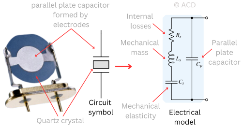 The crystal’s remarkable stability at a single frequency is due to its high Q factor, typically between 20,000 and 30,000. Because Cs and Cp are pretty small (in picoferads), the inductance (Ls) for resonance must be large, often in the range of several Henries. The Q factor for a series resonance circuit is the ratio of reactance to resistance. The resistance (Rs) is usually less than 100 Ω.
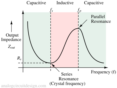
The graph above shows that crystals exhibit two resonance points: a lower impedance series resonance (also called crystal frequency), primarily determined by Cs and Ls, and a higher impedance parallel resonance, mainly influenced by Ls and Cp. At that frequency, Cs can be considered short.
Quartz crystal oscillator circuit
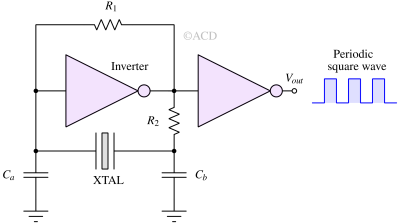
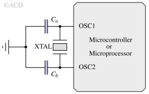
The quartz crystal is connected to an inverter and load capacitors Ca and Cb. The value of R1 ranges from 10kΩ to 10 MΩ. Due to R1 from input to output of the inverter, the output of the inverter lies somewhere at the mid-supply. This is a po\int where the inverter's gain is very high. The inverter provides 180 degrees of phase shift. For an oscillator to work, we need 360 degrees of phase shift. R2 and Ca, Cb give the rest of the phase shift.
The number of transistors used here is minimal (2 transistors per inverter), meaning less parasitic capacitor. This allows this circuit to be high-frequency capable. The second inverter is to isolate the oscillation-generating core from the uncertainties of the Vout node.
Calculation of load capacitance
$$C_{load}=\cfrac{C_aC_b}{C_a+C_b}+C_{stray}$$
Cstray represents the PCB stray capacitance, and the IC input capacitance is typically between 2pF and 10pF. Since this cannot be measured accurately, we must estimate it for a design. Changing the values of Ca and Cb will move the frequency up and down and affect the frequency accuracy at room temperature.
Equivalent series resistance
As XTAL packages become smaller, the maximum ESR value tends to increase. Therefore, ensuring that your oscillator circuit has enough gain to compensate for this increase in ESR is essential. Most common XTALs have ESR values below 100 Ω.
Crystal oscillator working principle
By applying an electrical signal to the quartz, we can get it to resonate at a frequency depending on its dimensions. For example, if we force a step voltage across a quartz crystal, the internal lattice structure is stressed and vibrates, causing a decaying sinusoidal current. We can achieve sustained oscillations if this current is amplified and fed back properly.
Crystal oscillator waveform
Crystal oscillators with inverters as amplifiers produce square waveforms at the output. Since square waves have sharp rise and fall, proper ground connections are necessary; otherwise, they can have large overshoots and undershoots. Minimizing lead inductance and trace inductance using bypass capacitors as close as possible to the clock source can achieve nearly ideal square pulses. A single transistor circuit or an opamp circuit creates a sinusoid waveform, which is used to create carriers for radio transmission.
Creating a Quartz crystal
The synthetic quartz bar made in an autoclave is sliced into thin wafers. The quartz is usually cut at an angle called an ‘AT’ cut, which is the standard cut. The cutting angle of the
quartz blank defines the behavior of the frequency over temperature (frequency stability). The cut quartz is then processed into round or rectangular parts and is now termed a ‘blank.’ The blanks are ground down to the thickness required for the needed specification. This process defines the resonant frequency.
Crystal oscillator performance
Standard quartz crystals have a frequency range from 32.768 kHz to over 200 MHz. Higher-frequency quartz crystals are usually available in more compact mounting sizes.
Stability of crystal oscillator frequency
The frequency stability describes the maximum frequency deviation over the operating temperature range. The quartz blank's cutting angle defines the frequency over temperature behavior.
The quality factor (Q) of crystal oscillators
The abbreviation Q stands for quality. This Q factor determines the frequency stability of the Crystal. A crystal’s Q factor typically ranges between 20,000 and more than 100,000. Sometimes, a crystal’s Q factor exceeds 200,000 and is also observable.
Oscillator noise performance
A widespread criterion required for an oscillator is its noise performance. It is measured using phase noise and jitter.
Crystal oscillator applications
Some applications of crystal oscillators are listed below :
Phase locked loops
A crystal oscillator is a stable reference clock for phase-locked loops. Some microcontrollers, like STM32, work at 72 MHz, while the crystal oscillator required for their operation is 8 MHz. The PLL helps to upscale the frequency to 72MHz using the internal VCO.
Crystal oscillator in Microcontroller
Crystal oscillator in Arduino
The crystal oscillator soldered onto the Arduino development board provides a square wave clock signal to the ATmega328 microcontroller. Generally, an Arduino board is equipped with a 16 MHz crystal. Arduino also has an internal 8MHz RC oscillator, which is less accurate than the 16MHz external crystal oscillator. The internal RC oscillator may vary in frequency due to the effects of temperature, humidity, and the manufacturing process.
Gas lighter
A piezoelectric material can ignite gases by generating a spark through an electric current. This setup involves two piezoelectric elements with opposite polarization aligned in a circuit with a spark gap. When mechanical force is quickly applied, it changes the polarization, causing charges to flow and create a spark at the gap, which can ignite the gas. The force must be applied rapidly; otherwise, the voltage dissipates as charges leak away.
Standard crystal oscillators/reference
The 32.768 KHz crystal
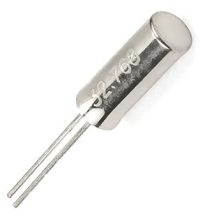
Real-time clock (RTC) applications have primarily relied on quartz crystals and oscillators with a frequency of 32.768 kHz. The number 32768 Hz is 215. A counter of 215 will take precisely 1 second to overflow. These crystals have a minimal form factor. These are also called watch crystals. They provide three advantages :
- Low power consumption due to lower frequency operation.
- Cost-effectiveness.
- Wide availability.
- Tight tolerance, high stability, and resistance to environmental factors.
The 8MHz and 16 MHz crystal
Most microcontroller systems, such as AVR (Arduino) and STM32, use an external 16MHz or 8MHz crystal to produce the timing information.
Crystal oscillator manufacturers
Some manufacturers are listed below :
- Bliley Technologies
- Abracon
- TXC corporation
- Murata
- IQD
- Wurth Electronics